


g
GE
OPM_SGS_ISG_M22_M30_0US_V011.doc 32/38 Installation Guide
SG Series
225 & 300 kVA
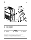
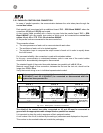
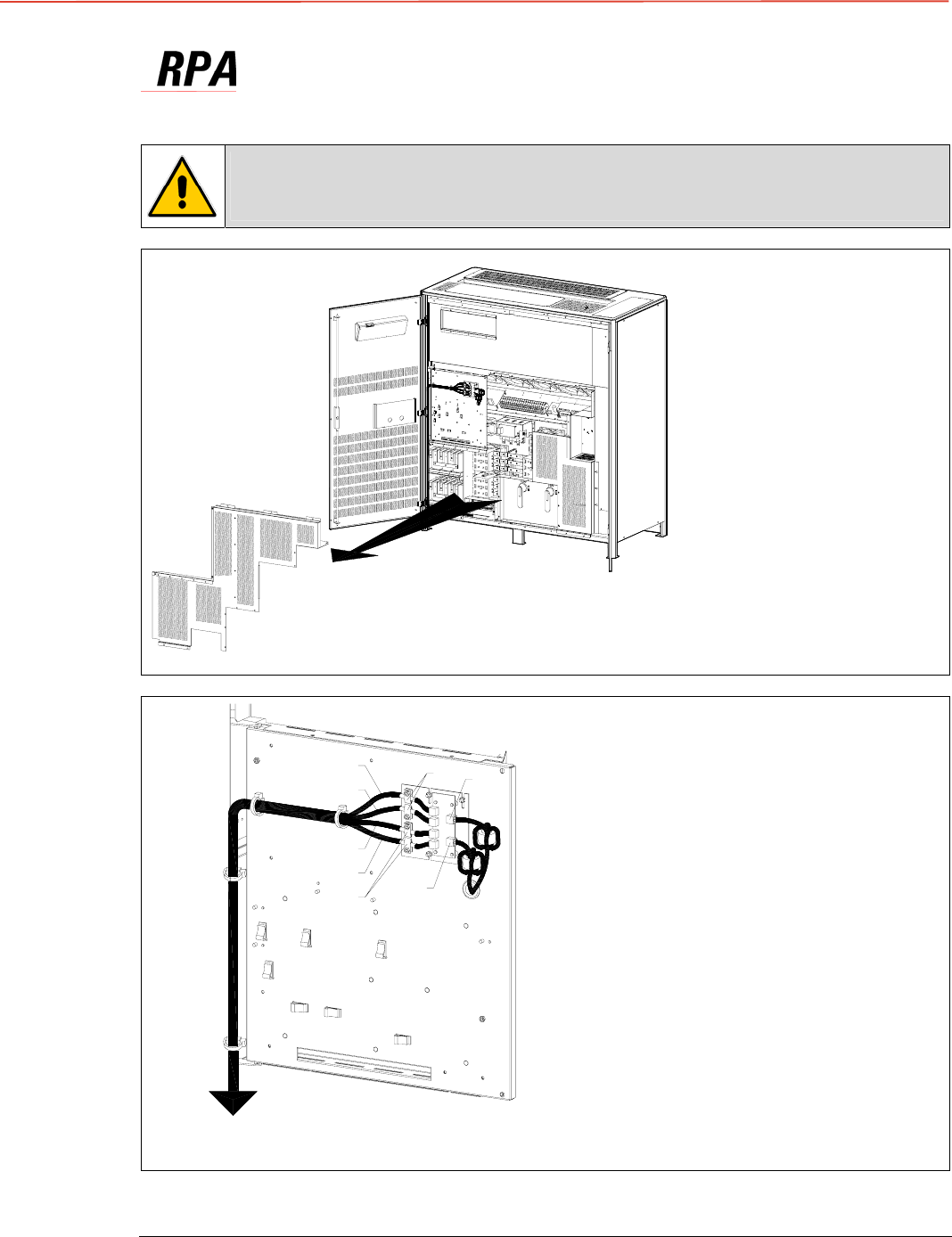
3.11 CONTROL BUS CABLE LOCATION
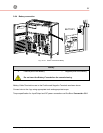
Warning!
This installation must be verified by trained personnel before the initial start-up
(ensure that the UPS installation is completely powered down).
SGS_225-300_RPA control bus cable_01
Q1
Q2
A
2
4
3
1
3
4
2
1
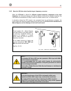
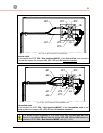
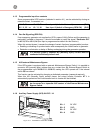
Fig. 3.11-1 View electronic module on intermediate unit
Access to the control bus
connection.
The control bus connection
between parallel units must be
made on the front of the
electronic module fitted
behind the front doors.
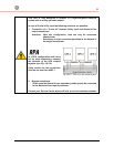
To properly route the control
bus cables the safety screen
“A” must be removed.
SGT5000_100-150_RPA control bus cable_02US
Next
p
arallel unit
JB2
JB1
JA2
JA1
A
A
JA
JB
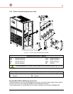
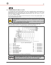
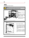
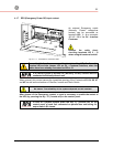
Fig. 3.11-2 Front view electronic module on intermediate unit
Control bus cables connection.
•
Plug the cables
JA
(1/2/3/4/5/6/7)
and JB (1/2/3/4/5/6/7) onto the RJ
connectors JA and JB
located on
parallel bus PCB “P34 – Bus
Interface IM0048” (going to “P13 –
RPA Board IM0006” J52(A) and
J62(B)).
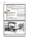
• Fix both cables JA (1/2/3/4/5/6/7)
and JB (1/2/3/4/5/6/7) to parallel bus
socket connecting the cable shield to
ground by means the cable clamps
“A“.