


CHAPTER 2: MECHANICAL INSTALLATION
6
EPM 5000 series Advanced Power Meters GE Multilin
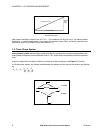
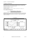
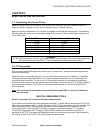
FIRST PUT (16) PIN
CONNECTOR TOGETHER.
(2) 8-32 SCREWS WILL
S
IDE VIEW
0.80
(4) 8-32 SCREWS
LINE UP WITH 2 PEMS
ON THE BACK PLATE.
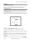
0.198 DIA.
3.375
3.375
4.0 DIA.
1.6875
1.6875
RECOMMENDED
CUTOUT
BACK VIEW
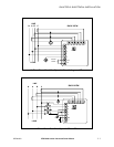
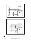
Diagram 2.3: Standard cutout
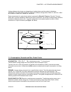
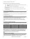
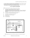
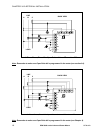
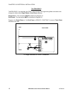
W Port
Diagram 2.4: Optional Communication Converter or DC Output Module Installation
* Recommended wire gauge is 20 AWG for DC Output or RS-485 options.
Note: Carefully line up the guide screw and 8 pin port connector to prevent pin breakage.