


CHAPTER 12: GROUPS 4, 5, AND 6 – SET LIMITS AND RELAYS
74
EPM 5000 series Advanced Power Meters GE Multilin
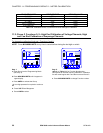
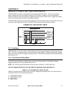
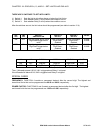
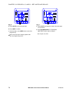
THERE ARE 3 SWITCHES TO SET WITH LIMITS:
1) Switch 1: Sets the limit to trip either above or below the Limit Value.
2) Switch 2: Sets whether Relay 1 will trip when the condition occurs.
3) Switch 3: Sets whether Relay 2 will trip when the condition occurs.
After the switches are set, the limit value should be programmed (see table in section 12.4).
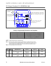
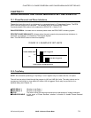
LM1
LED
LM2
LED
SWITCH 1
ABOVE/BELOW
SWITCH 2
RELAY 1
SWITCH 3
RELAY 2
VALUE
ON OFF Digit Up-trigger above value
Digit Down-trigger below
value
Digit Up-enabled
Digit Down-
disabled
Digit Up-enabled
Digit Down-
disabled
0-9999
0-9999
OFF ON Digit Up-trigger above value
Digit Down-trigger below
value
Digit Up-enabled
Digit Down-
disabled
Digit Up-enabled
Digit Down-
disabled
0-9999
0-9999
Table 12.5: Group 5: Functions 0–7
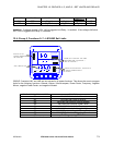
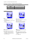
LM1
LM2 SWITCH 1 SWITCH 2 SWITCH 3 VALUE
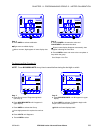
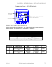
ON OFF Digit Up Digit Up Digit Down 0120
OFF ON Digit Down Digit Down Digit Up 0090
Table 12.6: Group 5: Example for Function 0
Thus, if Kilowatts exceed 120 W, LM1 is triggered and Relay 1 is tripped.
If the Kilowatts fall below 90 W, LM2 is triggered and Relay 2 is tripped.
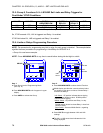
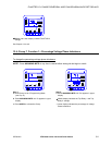
SPECIAL CASES
FREQUENCY: FUNCTION 4 contains a permanent decimal after the second digit. The highest and
lowest level limits that can be programmed are 99.99 and 00.00, respectively.
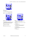
POWER FACTOR: FUNCTIONS 3 and 6 contain a permanent decimal after the first digit. The highest
and lowest limits that can be programmed are 1.000 and 0.000, respectively.