


CHAPTER 9: PROGRAMMING GROUP 0 – GLOBAL METER SETUP
GE Multilin EPM 5000 series Advanced Power Meters 47
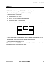
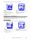
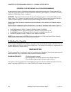
PACK SWITCH FEATURE SEGMENT POSITION
A Reserved —
B Reserved —
C Reserved —
0
D Phase Reversal Limit Detection UP: Enable
DOWN: Disable
A Non-significant will blank leading zero UP: Enable
DOWN: Disable
B Reset Protection
(see Part I: Installation and Operation)
UP: Enable
DOWN: Disable
C Phase Reversal Rotation Selection UP: CBA Rotation
DOWN: ABC Rotation
1
D Open Delta Installation
(see Part I: Installation and Operation)
UP: Enable
DOWN: Disable
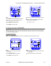
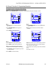
A Limit/Relay Control UP: Average
DOWN: Instantaneous
B Power Factor Polarity Indicates + (voltage referenced)
or
- (current referenced)
UP: -PF
DOWN: +PF
2
C, D For EI-BUS protocol: Switch C is DOWN, Switch D is DOWN.
For MODBUS protocol, ASCII framing: Switch C is UP, Switch D is UP.
For MODBUS protocol, RTU framing: Switch C is DOWN Switch D is UP.
For DNP 3.0 protocol: Switch C is UP, Switch D is DOWN.
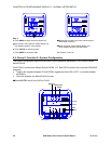
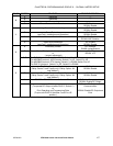
A Trip Relay Computer Control 1
(Relay Control 1 and 2 apply only if Relay Option -NL
was ordered.)
UP: Enable
DOWN: Disable
B Trip Relay Computer Control 2
(Relay Control 1 and 2 apply only if Relay Option -NL
was ordered.)
UP: Enable
DOWN: Disable
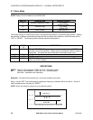
C
RS-232 or RS-485 Communications or Print UP: Enable Communications
DOWN: Enable DC Output
3
D
DC Output
(To operate DC Output, disable PACK 3, Switch C)
or
Print Operating and Programming Data
(To print, set PACK 3 Switches C and D to UP
position.)
UP: Enable DC Output or Print
Communication
DOWN: Disable DC Output and
Print
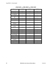
Table 9-2: System Configuration—Switch Packs for Group 0, Function 3