


CHAPTER 3: ELECTRICAL INSTALLATION
8
EPM 5000 series Advanced Power Meters GE Multilin
O
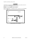
PTION 2: ISOLATING A CT CONNECTION REVERSAL USING VOLTAGE READINGS
! Remove potential connections to terminals 6 and 7. Observe the KW reading. It should
be positive.
! If negative, reverse the CT wires on terminals 8 and 9.
Connect terminal number 6 potential. If KW decreases to about zero, reverse CT wires on
terminals 10 and 11.
Connect terminal number 7 potential. If KW is one-third of expected reading, reverse CT wires to
terminals 12 and 13.
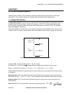
3.3: Connecting the Voltage Circuit
For proper meter operation, the voltage connection must be maintained. The voltage must correspond to
the correct terminal.
The cable required to terminate the voltage sense circuit should have an insulation rating greater than 600V AC and a
current rating greater than 0.1 A.
3.4: Selecting the Voltage Fuses
We strongly recommend using fuses on each of the sense voltages and the control power, although
connection diagrams do not show them. Use a 1 Amp fuse on each voltage input.
The meter can handle a maximum voltage of 150V phase to neutral. PTs are required for higher
voltages. Suffix -G extends the maximum direct voltage to 300V phase to neutral, 600 volt phase to
phase.
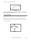
3.5: Connection to the Main Power Supply
The meter requires separate control power to operate. Listed are the five different power supply options
and corresponding suffixes.
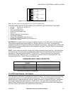
CONTROL POWER OPTION SUFFIX CURRENT
120V AC 115 A 0.1 AAC
240V AC 230 A 0.05 AAC
12V DC D4 0.10 ADC
24-48V DC D 0.25-0.5 ADC
125V AC/DC (universal) D2 0.10 AAC or DC
Table 3.2: Control Power and Current
Note: For DC-powered units, polarity should be observed. Connect the negative terminal to L and
positive terminal to L1. An earth ground connection to chassis is mandatory for normal
operation (terminal three). Do not ground the unit through the negative of the DC supply.
Note: Externally fuse power supply with a slow-blow 3 Amp fuse.
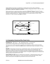
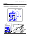
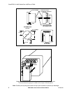
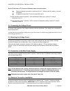
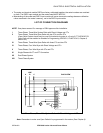
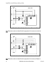
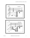
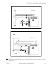
3.6: Electrical Connection Installation
Choose the diagram that best suits your application and maintain the CT polarity. Follow the outlined
procedure to verify correct connection. IMPORTANT: For PT connections only, short terminals 3 and 4.
Connect local ground to terminal 3. This protects the unit from spikes and transients.