


CHAPTER 12: GROUPS 4, 5, AND 6 – SET LIMITS AND RELAYS
76
EPM 5000 series Advanced Power Meters GE Multilin
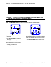
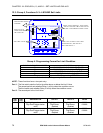
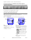
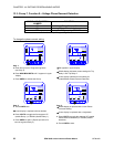
12.5: Group 6, Functions 0–5—LM1/LM2 Set Limits and Relay Triggers for
Over/Under %THD Conditions
LM1 LED LM2 LED SWITCH 1
ABOVE/BELOW
SWITCH 2
RELAY 1
SWITCH 3
RELAY 2
LEVEL
ON OFF Digit Up Digit Up Digit Down 012.0
OFF ON Digit Down Digit Down Digit Up 009.0
Table 12.9: Group 6—Example for Function 0
So, if THD exceeds 12%, LM1 is triggered and Relay 1 is enabled.
If THD falls below 9%, LM2 is triggered and Relay 2 is enabled.
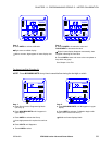
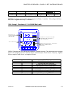
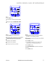
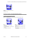
12.6: Limits or Relays Programming Procedure
NOTE: The procedure for programming any limit or relay for each group is identical. The example below
signifies the exact procedure for programming a Limit/Relay for GROUPS 4–6.
—Group 4 is used as an example.
NOTE: Press MAX/MIN/LIMITS at any time to cancel before storing the last digit or switch.
MAX/MIN
LIMITS
KVAR
PF
KW
KVA
FREQ
KWH
KVAH
AC VOLTS
AC AMPS
POWER
NC
B
A
MAX
MIN
A
N
B
N
C
N
A
B
B
C
C
A
LM2
LM1
NEXT
PHASE
VOLTS
AMPS
POWER
GROUP
MAX/MIN
LIMITS
KVAR
PF
KW
KVA
FREQ
KWH
KVAH
AC VOLTS
AC AMPS
POWER
NC
B
A
MAX
MIN
A
N
B
N
C
N
A
B
B
C
C
A
LM2
LM1
NEXT
PHASE
V
OLTS
A
MPS
POWER
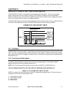
FUNCTION
RELAY
LIMIT
SWITCHES
V
ALUE
Step 1:
a. Enter Group Level of Programming Mode
(see Chp. 8).
b.
Press MAX/MIN/LIMITS until 4. appears in upper
display.
c.
Press AMPS to activate the Group.
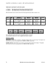
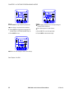
Step 2:
a. Press MAX/MIN/LIMITS to select desired Function.
! Middle display provides the currently selected value
for whether to trip above or below, activate Relay 1
and activate Relay 2.
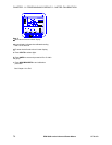
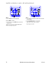
Left Switch
: UP position indicates above tripping
value for lower display’s value. DOWN position
indicates below tripping.
Middle Switch
: UP position sets Relay 1 to trip.
DOWN position doesn’t activate Relay 1 when limit
condition exists.
Right Switch
: Same as Middle Switch , regarding
Relay 2.
b. Press VOLTS to toggle between LM1 and LM2
settings.
! The LM1 or LM2 annunciator indicates the limit
being displayed.