


CHAPTER 16: ETHERNET OPTION
92
EPM 5000 series Advanced Power Meters GE Multilin
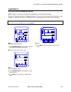
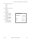
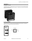
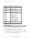
See the Table below for a description of the Status LED functions.
LED Description LED Functions
1 Serial Port
(Channel) 1
Status
Lights solid green to indicate Channel 1 is IDLE.
Blinks green to indicate Channel 1 is connected
to the network and ACTIVE.
2 Serial Port
(Channel) 2
Status
Lights solid yellow to indicate Channel 2 is IDLE.
Blinks yellow to indicate Channel 2 is connected
to the network and ACTIVE.
(Not used by this device; reserved for future use)
3 Diagnostics Blinks or lights solid red in combination with the
green (Channel 1) LED to indicate
DIAGNOSTICS and ERROR DETECTION.
Red solid, green (Channel 1) blinking:
1x: EPROM checksum error
2x: RAM error
3x: Network controller error
4x: EEPROM checksum error
5x: Duplicated IP address on network*
6x: Software does not match hardware*
Red blinking, green (Channel 1) blinking:
4x: Faulty network connection*
5x: No DCHP response received*
4 Network Link
Status
Lights solid green to indicate network port is
connected to the network.
* non-fatal error
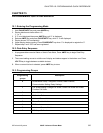
16.2: Ethernet Option Setup
This chapter covers the required steps to get the Ethernet Interface on-line and working. There is only
one method used to log into the Ethernet Server and set up the IP address:
• Network Port Login: make a Telnet connection to the network port (9999).
It is important to consider the following points before logging into and configuring the Ethernet Interface:
• The Ethernet Interface’s IP address must be configured before a network connection is available.
• Only one person at a time may be logged into the network port. This eliminates the possibility of
several people trying to configure the Ethernet Interface simultaneously.