


CHAPTER 12: GROUPS 4, 5, AND 6 – SET LIMITS AND RELAYS
72
EPM 5000 series Advanced Power Meters GE Multilin
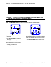
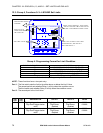
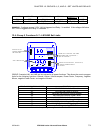
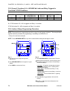
12.3: Group 4, Functions 0–3—LM1/LM2 Set Limits
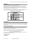
Group 4: Programming Format for Limit Condition
GROUP AND FUNCTION NUMBER FUNCTION
40.
LM1/LM2 Set Limits for Volts AN, BN, CN
41.
LM1/LM2 Set Limits for Volts AB, BC, CA
42.
LM1/LM2 Set Limits for Amps A, B, C
43.
LM1/LM2 Set Limits for Amps Neutral
4E.
Exit Programming GROUP 4
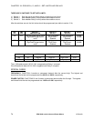
Table 12.1: Group 4 Programming Format
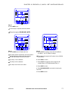
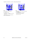
NOTE: These functions have a two-part entry:
Part 1: The first switch sets the limit to trip either above or below the Limit Value.
The second switch sets whether Relay 1 will trip when the condition occurs.
The third switch sets whether Relay 2 will trip when the condition occurs.
Part 2: The second part is the Limit Value.
LM1
LED
LM2
LED
ABOVE/BELOW RELAY 1 RELAY 2 VALUE
ON OFF Digit Up-trigger above value
Digit Down-trigger below
value
Digit Up-enabled
Digit Down-
disabled
Digit Up-enabled
Digit Down-
disabled
0-9999
0-9999
OFF ON Digit Up-trigger above value
Digit Down-trigger below
value
Digit Up-enabled
Digit Down-
disabled
Digit Up-enabled
Digit Down-
disabled
0-9999
0-9999
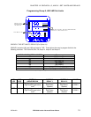
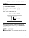
Table 12.2: Group 4: Functions 0–3
MAX/MIN
LIMITS
KVAR
PF
KW
KVA
FREQ
KWH
KVAH
AC VOLTS
AC AMPS
POWER
NCBA
MAX
MIN
A
N
B
N
C
N
A
B
B
C
C
A
LM2
LM1
NEXT
PHASE
VOLTS
AMPS
POWER
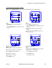
DESIGNATES GROUP
NUMBER.
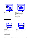
USE VOLTS TO
TOGGLE BETWEEN
LM1 AND LM2.
THE LIMIT VALUE.
SINCE THIS IS GRO UP 4, FUNCTION 0,
AN, BN & CN ANNUNCIATORS GLOW.
FROM LEFT TO RIGHT: SET LIMIT
AND TRIP RELAY 2.
THE LM1/LM2 SET LIMITS FOR VOLTS
ABOVE/BELOW, TRIP RELAY 1