


2. OPERATION LOGIC
GEK-106168E DBF Breaker Failure Protection 5
2.2. MONITORING AND RECORDING FUNCTIONS
2.2.1 MEASUREMENT
The DBF system provides the continuous measurement of phase and ground current values.
These measurements can be accessed directly on the liquid crystal display (HMI) on the front of the relay, or via
the GE-LOCAL communication software.
2.2.2 ASSOCIATED BREAKER STATUS
The DBF system monitors the associated breaker status through the digital inputs 52/b (or 52/a), and it is
displayed on the local HMI or through the communications software.
2.2.3 TARGET LAMPS
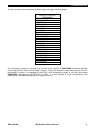
The DBF incorporates 17 LED target lamps, one fixed LED (two colors) assigned to the system ready function,
and 16 user configurable red LEDs. These configurable LEDs are arranged in two columns of 8 LEDs each. The
configuration is done using the GE-INTRO software, and it consists on assigning an internal event (or an AND
gate of internal events) to an LED. The LED can be configured to have memory (if Vdc is removed or the event
causing the operation of the LED gets deactivated) or not and to blink or to be steady. The internal events must
be previously defined using the internal signals of the relay. It is possible to use AND, OR and NOT logic gates to
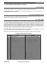
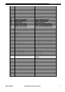
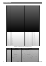
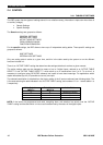
define these events. The available internal signals are listed in the following table.
The TARGET RESET button allows testing all target lamps if it is pushed for a short time (lighting up all of them),
or resets the sealed-in targets if it remains pressed for three seconds or more.
Please refer to GE_INTRO (configuration software) Instruction book (GEK-105594) for further information.
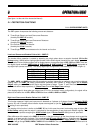
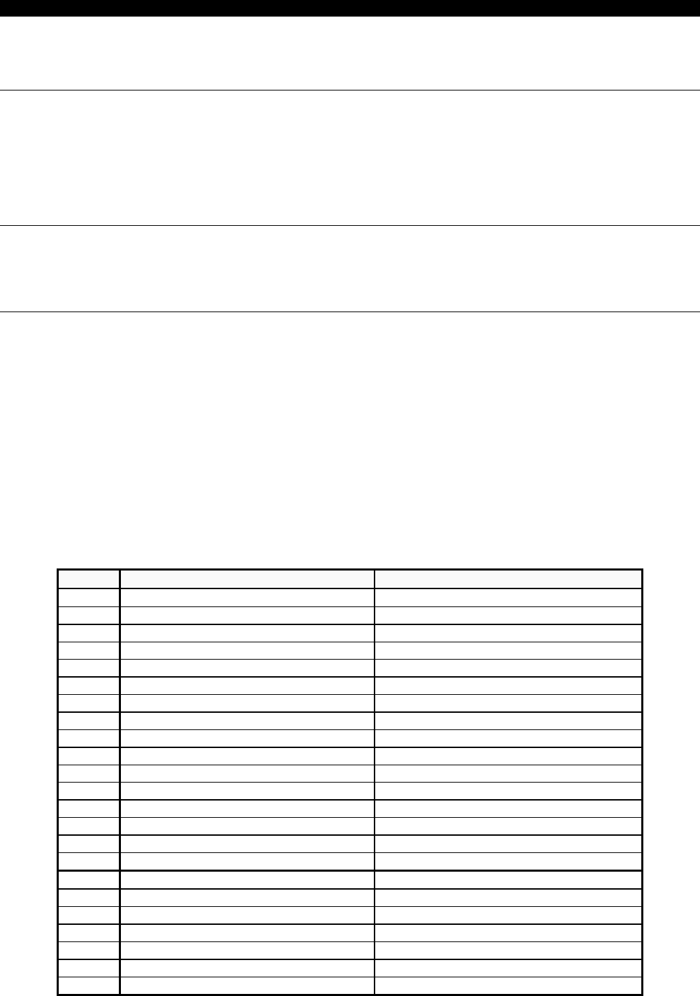
INTERNAL PROTECTION STATUS SIGNALS
Group Status Comment
1.0 Program Initiate Relay starts running (Vdc just applied).
1.1 Settings change User changes any setting
1.2 Write Counters User sets a value for any counter
1.3 Configuration Change User changes relay configuration
1.4 External Trigger Oscillography triggered by Dig. Input
1.5 Communications Trigger Osc. triggered by HMI or GE_LOCAL
1.6 Reset Operation Latched Relays Reset received
1.7
1.8
1.9
1.10
1.11
1.12
1.13
1.14
1.15
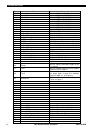
2.0 Input Nº 1 Digital Input #1 Status
2.1 Input Nº 2 Digital Input #2 Status
2.2 Input Nº 3 Digital Input #3 Status
2.3 Input Nº 4 Digital Input #4 Status
2.4 Input Nº 5 Digital Input #5 Status
2.5 Input Nº 6 Digital Input #6 Status
2.6