


2. OPERATION LOGIC
14 DBF Breaker Failure Protection GEK-106168E
2.4.3.2 Outputs
The basic DBF system has 10 outputs as follows:
• 2 tripping contacts (A12-B12 and C1-D1)
• 1 Breaker failure pickup signaling (A11-B11)
• 1 Internal arc detection (C2-D2)
• 1 Equipment alarm (C3-D3)
• 5 configurable contacts (C4-D4 to C8-D8)
The optional expansion board for the DBF provides 6 additional latched contacts (E1-F1 to E6-F6). This outputs
are not configurable and are assigned as follows:
• 3 tripping contacts (TRIP 1st Stage) (E1-F1 to E3-F3)
• 3 tripping contacts (TRIP 2nd Stage) (E4-F4 to E6-F6)
The configurable outputs can be programmed using logic based on the internal protection states (pick-ups, trips,
alarms, etc.). The DBF has 66 different internal states, and these can be used to carry out logical operations NOT,
AND and OR, which gives the unit a great flexibility.
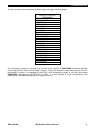
The output configuration is done using different levels. At the first level it is possible to use AND gates of up to 16
signals. The output is incorporated into the states matrix so that it can then be used in other AND gates of up to 16
inputs. This process can continue until the 16 ANDs are used.
Once the AND gates have been configured it is possible to create a second level with OR gates of 16 inputs
limited to the established groups of bytes, and whose logical outputs are assigned to physical outputs of the unit.
This means that we can configure the physical outputs with any internal signal from the status or any combination
of them made by means of the AND logic gates.