


6. ACCEPTANCE TESTS
GEK-106168E DBF Breaker Failure Protection 29
6.
6. 6.
6. ACCEPTANCE TESTS
ACCEPTANCE TESTSACCEPTANCE TESTS
ACCEPTANCE TESTS
6.1. CONNECTIONS AND NECESSARY EQUIPMENT
Necessary equipment:
• One current source
• One DC voltage source
• Precision timer for testing timed events
• One AC/DC voltmeter/ammeter
Connect the relay as indicated in the external connections diagram, Figure 2.
For safety reasons, the external protection earth should be securely grounded.
Apply dc rated voltage to terminals A10-B10
6.2. VISUAL INSPECTION
Check that the relay has not suffered any kind of damage due to transport and handling.
Check that all the screws are tight and the terminal blocks have not been damaged in any way.
6.3. PANEL INSULATION TESTS
!
If any insulation test would be performed on the panel where the relay is installed, the ground terminals
A9-B9 must remain ungrounded.
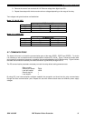
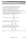
Do the following groups in the terminals of the relay:
Group 1: A10, B10
Group 2: A1 to A4, B1 to B4
Group 3: C9, C10, D9, D10, C11, C12, D11, and D12
Group 4: A11, B11, A12, and B12
Group 5: C1, D1, C2, D2, C3, and D3
Group 6: C4, C5, C6, C7, C8, D4, D5, D6, D7, and D8
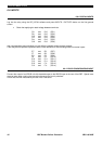
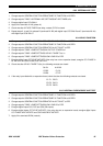
If the relay has expansion board, then the following groups must be added:
Group 7: E7, F7, E8, F8, E9, F9, E10, F10, E11, F11, E12, and F12
Group 8: E1, F1, E2, F2, E3, F3, E4, F4, E5, F5, E6, and F6
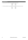
Apply 2000V gradually between case and groups.
Apply 2000V gradually between groups.