3. SETTINGS
GEK-106168E DBF Breaker Failure Protection 17
3.
3. 3.
3. SETTINGS
SETTINGSSETTINGS
SETTINGS
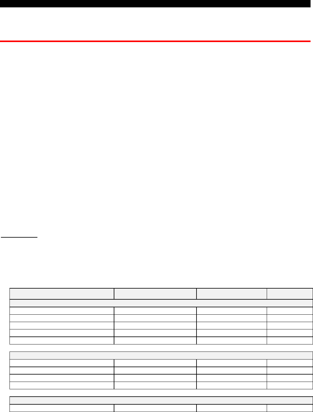
This section describes the settings of the DBF relay and the procedure to modify them. Table 3 shows the list of
DBF settings, their range and resolution, and the factory default settings.
To view or to modify settings using the GE_LOCAL program connected to PORT 1, PORT 2 or PORT 3 the user
has to perform the following steps:
• Check that the available connection cable is in accordance with the diagram in Figure 7.
Check correspondence between DB-9 connector in the cable with available connector at PC
port (could be DB-9 or DB-25)
• Connect the cable between the relay (or modem) and the serial port of your computer.
• Run the GE-LOCAL software. For more details on the installation and use of the GE-LOCAL
software see instruction book GEK-105568.
• Make sure that the communication parameters in GE_LOCAL match with those set on the
DBF. Specifically, the parameters on the configuration of the local HMI are:
∗
COMMUNICATION SPEED
: On the relay depending on whether communication is:
through PORT 1 or PORT 2 (means LOCAL), or PORT 3 (means NET)
∗
STOP BIT
: Stop-bit corresponding to each one of the communication ways: LOCAL or
NET
To modify or view the DBF communication parameters refer to Chapter 8, Section 8.1 “Menu Tree”.
IMPORTANT: It should be noted that in order to simplify the setting of the unit and for safety reasons, all settings
related with the configuration of the unit (configurable inputs and outputs, internal status events and target LED’s)
have been removed from the HMI facilities and also from the communications software GE_LOCAL. To perform
these configurations the GE_INTRO software (described in instruction book GEK-105569) must be used.
TABLE 3. Settings Table
Common to all tables Range Default Step
General Settings Group
Relay status In/out of service In-service
Identification 20 ASCII characters No ID
Frequency 50 / 60 Hz 50 Hz
Phase CT Ratio 1-4000 1 1
Neutral CT Ratio 1-4000 1 1
Breaker Setting Group
Breaker Number 4 ASCII characters 0000
kI
2
t Operation Mode Fixed-Measured Fixed
Integration Time for kI
2
t 0.03-0.25s 0.06s 0.01s
kI
2
t Maximum Limit 1-999999 99999 1
Active table setting group
Active setting table # 1 - 3 1 1


