8. KEYBOARD AND DISPLAY
42 DBF Breaker Failure Protection GEK-106168E
8.1. MENU TREE.
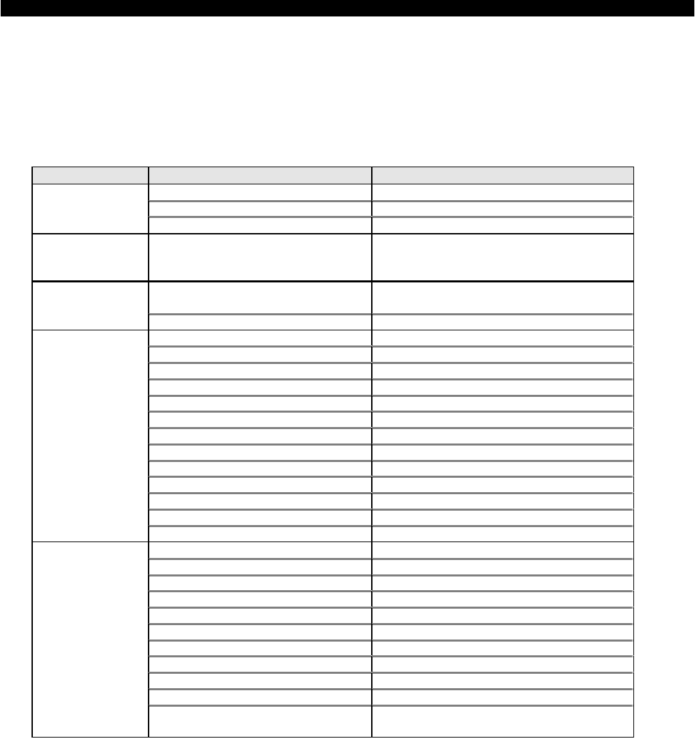
The DBF has different menus divided into levels. The Level 0 is the steady state screen. The Level 1 of the
different menus is accessed by pressing the corresponding group key (SET, INF, etc.). The scrolling within a
given level is done by using the UP and DOWN arrows. It is possible to go down to levels 2 and 3 by pressing the
ENT key. Press CLR to go up a level within the menu tree. The Level 1 for each of the five groups is shown in the
following table :
Group Level 1 Description
VIEW SETTINGS View settings
CHANGE SETTINGS Change settings
SET
CHANGE COUNTER Change counters
INF
STATUS Shows the status of the relay
SET DATE/TIME Change date and time
ACT
TRIGGERING Triggers the oscillography
I
a
Ia current in primary Amps
I
n
In current in primary Amps
I
2
t A COUNTER Accumulated kA
2
sec. for phase A
Nº OPENINGS Accumulated number opens
3/2-Phase Logic Shows logic for 50BF High Set.
50BF Pickup Shows status of 50BF
Relay ON/OFF Relay ON/OF condition
52A Status Breaker Pole A (open/closed)
52B Status Breaker Pole B (open/closed)
52C Status Breaker Pole C (open/closed)
LATCHING RELAY 1 Status Latching Relay 1 (open/closed)
LATCHING RELAY 2 Status Latching Relay 2 (open/closed)
ENT
DATE & TIME Shows date and time
NETWORK SPEED PORT3 (remote) comm. Speed
NETWORK STOP BITS PORT3 (remote) Stop bits
LOCAL SPEED PORT1&2 (local) comm. Speed
LOCAL STOP BITS PORT1&2 (local) Stop bits
LOCAL SETTINGS Local settings change allowed
REMOTE SETTINGS Remote settings change allowed
LOCAL OPERATION A Local operations allowed
REMOTE OPERATIONS Remote operations allowed
UNIT NUMBER Number of the unit
PASSWORD View/Change comm. Password
Hidden menu, typing this
code:
7169
t TIME-OUT Max. t between 2 synch signals (only for
relays in DDS integrated systems)


