


GFK-1852 Chapter 6 Serial Line Interfaces 6-3
Serial Line Interfaces
6
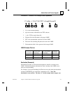
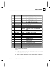
Item
Component
Name Purpose
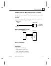
1 Screw terminal RXD or
RXA
RS-232: RXD (Received Data)
RS-422/485:RXA (Received Data -)
2 Screw terminal CTS or
RXB
RS-232: CTS (Clear to Send)
RS-422/485: RXB (Received Data +)
3 Screw terminal RTS or
TXB
RS-232: RTS (Request to Send)
RS-422/485: TXB (Transmit Data +)
4 Screw terminal TXD or
TXA
RS-232: TXD (Transmit Data)
RS-422/485: TXA (Transmit Data -)
5, 6, 7 Screw terminal NC No connection
8 Screw terminal GND Signal ground
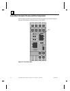
9 Reset switch RESET Push to power reset and initialize
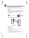
10 LED (Red) Fault or
Configurati
on
SOLID: Fault in VMSE communication
(read error) or VMSE is in Configuration
Mode
11 LED (Green) Ready SOLID: Connection to network host
established
12 LED (Yellow) Activity FLASHING: Network traffic
13 LED (Green) Link SOLID: VMSE has good Ethernet link
14 Connector (RJ45) Ethernet
port
RJ45 connector for Ethernet 10BaseT
15 Connector (RJ45) Serial port RJ45 connector for RS-232
16 LED (Yellow) Serial TXD FLASHING: Indicates transmission
from the serial port
17 LED (Yellow) Serial RXD FLASHING: Indicates reception
to the serial port
18 Switch Switch for
screw block
UP: Serial RS-232
DOWN: Serial RS-422/485
19 Screw terminal DC + Operating power, positive
20 Screw terminal Ground Earth ground
21 Screw terminal DC - Operating power, negative
22 Screw terminal Ground Earth ground
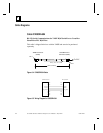
Figure 6-3. Front Panel Components
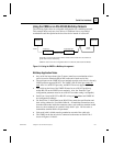
NOTEs:
•
For RS-485 2-wire functionality, pins 1 & 4 and 2 & 3 of the screw terminals
must be connected together.
•
The RJ-45 Ethernet connector uses industry standard 10Base T connections.