


Index
GFK-1852 Index-1
A
ARP, 4-3
command example, 1-4
Automatic connection address,
4-12
B
Baud rate configuration, 4-9
Broadcast address, A-2
Buffer flushing, 4-15
C
Cable diagrams, 6-4
Class A network, A-1
Class B network, A-1
Class C network, A-2
Configuration
memory, 4-1
parameters, 4-4
Telnet, 4-9
Configuration setup
SRTP/SNP, 4-5
Connect mode, 4-12
Connections
terminal screw, 6-3
Connector, VMSE
pin-out, 6-1
Controller
specifications, 7-1
CPU
specifications, 7-1
D
Datagram mode, 4-13
DHCP, 4-2
Diagrams
cable, 6-4
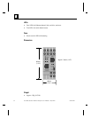
front panel layout, 6-2
Dimensions, 7-2
Disconnect mode
DTR disconnect, 4-14
E
Ethernet, 2-2
External transceiver, 2-2
F
Firmware
download from VMSE to
VMSE, 5-4
download via network host, 5-4
downloading via serial port, 5-2
VMSE options, 1-2
Flow control config., 4-10
Force Telnet mode, 4-14
Front panel layout
of VMSE, 6-3
G
Gateway IP address, 4-9, 4-18
I
IC200CBL504
serial cable, 6-4
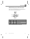
IC690ACC901 Miniconverter
9-pin pin-out, 6-15
cable, 6-5
Inactivity timeout, 4-15
Interface Mode config., 4-10
IP address, 3-2, 4-6, 4-9, 4-17,
A-2, A-3
factory default, 4-2
forcing new IP, 4-2
remote, 4-11
IP addressing, A-1
IP Networks
private, A-3
L
Layout
VMSE front panel, 6-3