


GEH-6385 Reference and Troubleshooting, 2300 V Drives Chapter 3 Paramters/Functions
•
••
•
3-53
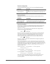
Function configuration
The following table specifies the DC Link Protection configuration parameters.
Parameter Description
DC bus region max High boundary of user specified DC link voltage region.
DC volts
DC bus region min Low boundary of user specified DC link voltage region. DC
volts
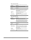
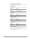
Faults and alarms
The following table specifies the faults and alarms associated with the DC Link
Protection.
Fault/Alarm Description
DC bus over voltage Trip fault that occurs when the DC link voltage is too high.
DC bus under voltage Trip fault that occurs when the DC link voltage is too low.
DC bus voltage low Alarm that occurs when the DC link voltage is too low.
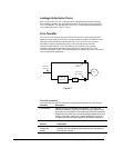
Function description
The signal DC bus feedback is an unfiltered representation of the DC link voltage.
DC bus voltage is a filtered version of the DC link voltage. The default filter
frequency is 90 rad/sec.
The DC bus over voltage trip fault occurs when the DC link voltage exceeds a
maximum safe operating voltage defined as
123% x
2
x 2300 Volts.
The DC bus under voltage trip fault occurs when the drive is running and the DC
link voltage falls below a minimum operating voltage. The DC bus voltage low
alarm occurs when the drive is stopped and the DC link voltage falls below a
minimum operating voltage. In both cases the minimum voltage is defined as
50% x
2
x 2300 Volts.
The DC bus voltage low alarm clears when the DC link voltage rises again to an
acceptable operating level.
The user has the opportunity to specify a desired operating region for the DC link
voltage. Parameters DC bus region max and DC bus region min define the high and
low boundaries of the region, respectively. The diagnostic variable DC bus excursion
indicates whether the DC link voltage lies within the region, and if not, how far
outside the region it falls.
If DC bus region min <= DC bus feedback <= DC bus region max,
DC bus excursion = 0.
If DC bus feedback < DC bus region min,
DC bus excursion = DC bus feedback - DC bus region min.
If DC bus feedback > DC bus region max,
DC bus excursion = DC bus feedback - DC bus region max.
Notice that if the DC link voltage falls below the user specified region, DC bus
excursion is negative; if the DC link voltage falls above the region, DC bus
excursion is positive.