GEH-6385 Reference and Troubleshooting, 2300 V Drives Chapter 3 Paramters/Functions
•
••
•
3-69
Faults and alarms
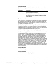
The following table specifies the faults and alarms of the Phase Imbalance Monitor
function.
Fault/Alarm Description
AC line transient This alarm occurs as a result of significant phase lock loop
error or significant phase imbalance.
AC line watchdog This trip fault will occur when the AC line transient alarm
persists for about one second. Both the trip fault and the alarm
are a result of significant phase lock loop error or significant
phase imbalance.
Function description
Phase imbalance sqr is fundamental to the Phase Imbalance Monitor function. It is
the filtered sum of two squared signals. The first is PLL error and the second is the
difference between X axis line voltage and AC line magnitude. Phase imbalance sqr
is a measure of the imbalance of the ac line.
The Phase Imbalance Monitor function compares Phase imbalance sqr to its allowed
threshold (variable Phase imbalance ref) to create the delta above the threshold
(variable Phase imbalance avg). If Phase imbalance avg is positive, it accumulates
with dt compensation in an integrator (variable Phase imbalance int). The integrator
is clamped by an upper threshold (variable Phs imbalance limit).
If the Phase imbalance int integrator exceeds the clamp threshold, the AC line
transient alarm will occur. If this condition persists for Phs imbalance time Seconds,
the AC line watchdog trip fault will occur.
The Phase Imbalance Monitor function has a direct effect on the Phase Lock Loop
function. The PLL proven boolean indicates the status of the Phase Lock Loop
function. When the control first detects the ac line, a significant, transient error is
present until the loop locks. Phase imbalance avg will thus be significant, but will
begin to decay as the loop locks. After Phase imbalance int is less than zero for
about 120msec, PLL proven will be set true and the phase lock loop will be declared
ready for use. In order for PLL proven to be set False after it is set True, AC line loss
must be true for 1 Seconds or Phase imbalance int must be non-zero for 1 Seconds.
If the ac line drops below 10% of nominal for 5msec, AC line loss will be set True,
declaring that the ac line has been lost. This will immediately cause the AC line
transient alarm. If the condition persists for 1Seconds, the drive will trip if it has not
already done so. AC line loss will be set False again as soon as the ac line rises back
above 15% of nominal.
Related functions
• Phase Lock Loop
Related diagrams
• Line Monitor Overview (Ovr_Lin_Mon)


