


3-26
•
••
•
Chapter 3 Paramters/Functions Innovation Series Medium Voltage GP Type - G Drives GEH-6385
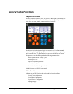
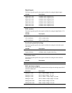
The variables displayed by the meters and the meter ranges can be modified by
configuring the following parameters:
Function configuration
Parameter Description
Keypad meter 1 sel Selects a floating-point variable that is displayed in
Meter #1 on the DDI Status screen.
Keypad meter 2 sel Selects a floating-point variable that is displayed in
Meter #2 on the DDI Status screen.
Keypad meter 3 sel
Selects a floating-point variable that is displayed in
Meter #3 on the DDI Status screen.
Keypad meter 4 sel
Selects a floating-point variable that is displayed in
Meter #4 on the DDI Status screen.
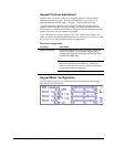
Keypad meter 1 range Selects the bar graph meter scaling for Meter #1.
Possible values are as follows (note that all bar
graphs are scaled in percent (%)):
0 to +100
-100 to +100
0 to +150
-150 to +150
0 to +200
-200 to +200
0 to +300
-300 to +300
Keypad meter 2 range Selects the bar graph meter scaling for Meter #2.
See Keypad meter 1 range for possible values.
Keypad meter 3 range
Selects the bar graph meter scaling for Meter #3.
See Keypad meter 1 range for possible values.
Keypad meter 4 range
Selects the bar graph meter scaling for Meter #4.
See Keypad meter 1 range for possible values.
Keypad meter 1 ref Selects an optional reference display for Meter #1. If
selected, the bar graph for this reference signal will be
displayed just above the bar graph for the feedback
signal. Both graphs will be displayed in the Meter #1
area as a split screen. The reference signal will only
be displayed if local mode is enabled. Keypad meter 1
ref can be disabled from the pick list.
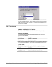
Note When changing DDI meter configuration from the toolbox, first save the
modified parameters to the drive. Press the Menu button and then the Status button
on the DDI. This will cause the meters on the Status screen to update.