


3-72
•
••
•
Chapter 3 Paramters/Functions Innovation Series Medium Voltage GP Type - G Drives GEH-6385
Phase Lock Loop
The Phase Lock Loop function outputs magnitude, frequency, and phase information
to the rest of the control, including the Line Monitor. A few configuration parameters
are critical. See the parameters in the function configuration section.
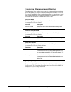
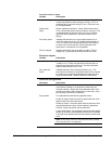
Function inputs
The following table specifies the input variables of the Phase Lock Loop function.
Variable Description
Y axis line voltage
The feedback for the phase lock loop regulator. The
reference is zero, since the phase lock loop is attempting to
regulate the y-component of the line voltage to zero. This
variable is also used with X axis line voltage to calculate the
AC line magnitude (variable AC line voltage mag).
X axis line voltage The demodulated x-axis component of the ac line voltage. It
is not used in the actual phase lock loop regulator, but is
used with Y axis line voltage to calculate the AC line
magnitude, AC line voltage mag.
PLL error The phase lock loop regulator error.
PLL prop gain The phase lock loop proportional gain. This gain is dynamic.
It very hot before the pll is locked and then changes to a
more sluggish gain.
PLL integral gain The phase lock loop integral gain. This gain is dynamic. It is
very hot before the pll is locked and then changes to a more
sluggish gain.
PLL max frequency
Maximum frequency allowed by phase lock loop regulator.
This is function of the nominal input frequency.
PLL min frequency Minimum frequency allowed by phase lock loop regulator.
This is function of the nominal input frequency. It is also
dynamic. When the pll is not locked, this variable is set to
the negative of PLL max frequency.
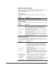
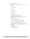
Function outputs
The following table specifies the output variables of the Phase Lock Loop function.
Variable Description
Line monitor frq A low-pass filtered version of the phase lock loop frequency
(variable PLL frequency). It is used for frequency fault
checking.
PLL frequency
The main un-filtered ac line frequency, as determined by the
phase lock loop regulator. This value is used throughout the
control’s regulators.
Elect angle command
This is the angle of the ac line as determined by the phase
lock loop regulator. It is the angle used to determine the
phase of the up/down commands to the bridge gating
interface.
Electric angle fbk This is the angle of the ac line as determined by the phase
lock loop regulator. It is the angle used to demodulate the
voltage and current feedbacks at the beginning of each fast
execution task.