


GE Zenith Controls 17
■
ZBTS / ZBTSD Operation and Maintenance Manual (71R-4000A)
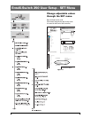
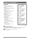
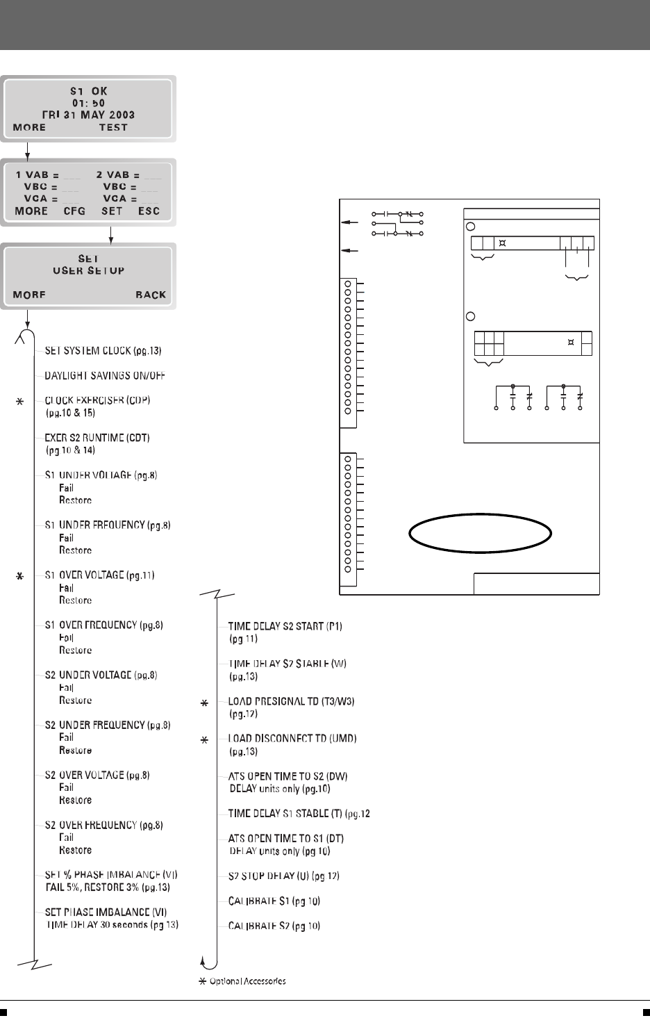
Entelli-Switch 250 User Setup - SET Menu
Change adjustable values
through the SET menu.
Enter six digit access code
(The factory assigned six-digit access code
is located on the back of the controller)
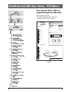
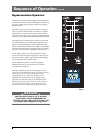
Figure 11
1
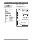
Engine Start Relay (De-Energized)
Network Communications
(Option)
1
2
3
4
5
6
7
8
9
10
11
12
13
14
15
16
J2
*
PROG 1
PROG 2
GRD (Input Sink)
NIA OUT
ELEV. PRE. OUT
ALARM OUT
MOTOR DISC. OUT
INHIB.>S1
INHIB.>S2
Input and output availability
subject to factory configuration.
*
1
2
3
4
5
6
7
8
9
10
11
12
13
14
J4
*
+12v (Output Source)
LN OUT
L4 OUT
L3 OUT
L2 OUT
L1 OUT
YN IN
YE IN
TSNL IN
Q2/TSL IN
S12 IN
Lithium Battery
Exerciser Battery
Replacement-K-4100 (BR2032)
Service Life-10 Years
† During normal operation
User Access Code
Default-121212
PRODUCT INFORMATION
www.geindustrial.com
24-Hour Service
(773)299-6600
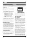
Entelli-Switch MX250
A2
(-)
A1
(+)
RELAY
14 11 12
Customer
Input
Voltage
COM
J2-3
N.O N.C
To
J2/J4
Inputs
WARNING
1
Controller Inputs must be relay Isolated.
2
Controller Outputs have Limited Source Capacity.
Use only GE Zenith-specified Output Modules.
11 14
R1
A1
(+)
12
21 24 22
A2
(-)
Output
Contacts
22
R1 Output
R1 Output
Contact Rating: 10A @ 250 VAC or 30 VDC
2
3
4
5
6
2421121411
LS OUT
STE OUT
TMS IN
LS IN
S5 IN
TM