


GE Zenith Controls 19
■
ZBTS / ZBTSD Operation and Maintenance Manual (71R-4000A)
Testing
ATS Testing
Start generator and verify proper voltage, frequency and phase
sequence (match to Source 1). Shut down gen set and place in
Auto. Complete the visual inspection of the transfer switch, and
close the cabinet door.
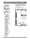
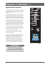
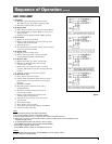
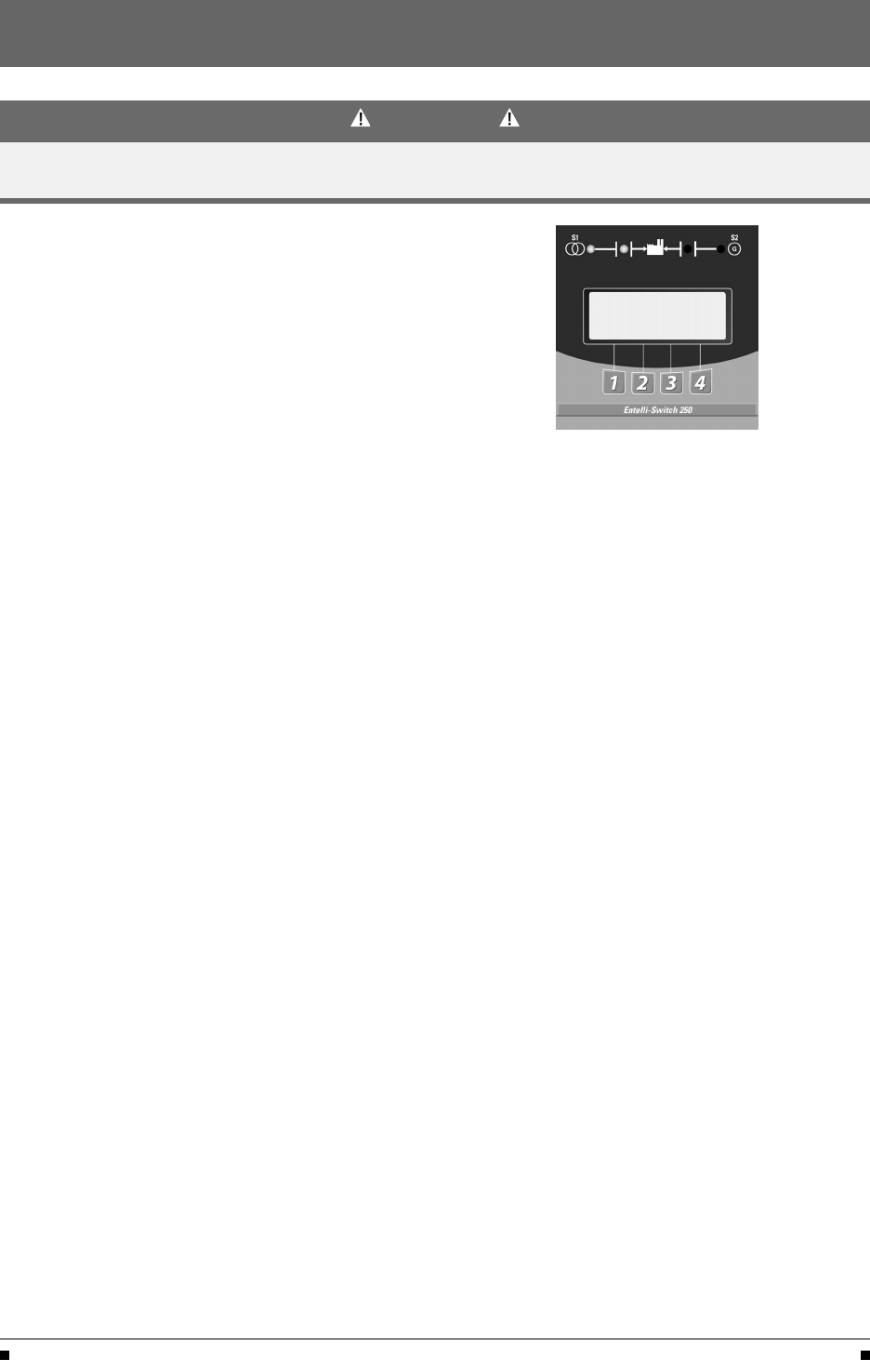
Initiate the test by pressing the TEST button on the LCD
keypad. The controller will then prompt for your access code.
After entering the code, three test options will appear—
XFR LOAD, FAST TEST and NO XFR (See Figure 12).
• XFR LOAD test starts the generator and using the
current timer settings, transfers the load to Source 2.
• FAST TEST test presets timer values to a maximum
30 seconds during the test. After completion of
the test, all timers are reset to their original
values. (T3, W3, DT and DW remain)
• NO XFR test starts the generator but does not
transfer the load to the Source 2.
Press and hold the desired test option button until the switch
transfers to Source 2 (load test) or until the generator has been
run for the desired amount of time (no load test). Releasing
the test button before W timer timeout will abort the test
(Exception: when the transfer commit option, is configured “ON”).
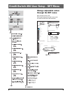
To test lamps, press TEST then scroll through MORE, then
press LAMP TEST. To cancel LAMP TEST press MORE.
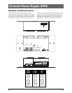
Standard Transition
When the test is initiated, the controller initiates the Time Delay
Source 2 Start Timer (Engine Start Timer "P") cycle. A manual
CANCEL button is provided to cancel the test if desired. Upon
completion of the (P) time delay, an Engine start Signal is sent to
Source 2. When Source 2 voltage and frequency reach the preset
"Restore" Values, the time delay to Source 2 Timer (W) begins its
timing cycle to ensure voltage and frequency stabilization before
transfer. A manual pushbutton BYPASS is provided to bypass the
"W" time delay if desired. After the (W) time delay, the MX con-
troller initiates a transfer signal through the SCR-E to operate
the main transfer operator. The load is now transferred to
Source 2 line. The transfer switch is mechanically locked. SN
limit switch awaits the next operation to Source 1.
Restoration of Source 1 Power:
Deactivating the test switch initiates re-transfer to Source 1
sequence. The delay to Source 1 Timer (T) begins its timing cycle
to ensure voltage and frequency stabilization before retransfer.
A manual pushbutton BYPASS is provided to bypass the "T"
time delay if desired. After the (T) time delay, the MX controller
initiates a transfer signal through the SCR-N to operate the
main transfer operator. The load is now transferred to Source 1
line. The transfer switch is mechanically locked. SE limit switch
awaits the next operation to Source 2.
Figure 12
Immediately after re-transfer, the S2 Stop Delay Timer (Delay
to Engine Stop "U") begins its cycle to allow Source 2 Engine
to run unloaded. A manual pushbutton BYPASS is provided to
bypass the "U" time delay if desired. Upon completion of the
(U) timing cycle, the controller sends an Engine stop signal.
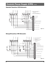
Delayed Transition
Source 1 Power Failure:
When the test is initiated, the controller initiates the Time
Delay Source 2 Start (Engine Start Timer "P") cycle. A manual
CANCEL button is provided to cancel the test if desired Upon
completion of the (P) time delay, an Engine start Signal is sent
to Source 2. When Source 2 voltage and frequency reach the
preset "Restore" values, the time delay to open Source 1 timer
(W) begins its timing cycle to ensure voltage and frequency sta-
bilization before re-transfer. A manual pushbutton BYPASS is
provided to bypass the "W" time delay if desired. After the (W)
time delay, the MX controller initiates a transfer signal through
the SCR-NO to operate the main transfer operator. The load is
now transferred to the Open position. The time delay to
Source 2 timer (DW) begins its timing cycle. After the (DW) time
delay, the MX controller initiates a transfer signal through the
SCR-E to operate the main transfer operator. The load is now
transferred to Source 2 line. The transfer switch is mechanically
locked. SN limit switch awaits the next operation to Source 1.
Restoration of Source 1 Power:
Deactivating the test switch initiates re-transfer to Source 1sequence.
The delay to open Source 2 Timer (T) begins its timing cycle to
ensure voltage and frequency stabilization before retransfer. A
manual pushbutton BYPASS is provided to bypass the "T" time delay
if desired. After the (T) time delay, the MX controller initiates a
transfer signal through the SCR-EO to operate the main transfer
operator. The load is now transferred to the Open position. The
time delay to Source 1 timer (DT) begins its timing cycle. After the
(DT) time delay, the MX controller initiates a transfer signal through
the SCR-N to operate the main transfer operator. The load is now
transferred to Source 1 line. The transfer switch is mechanically
locked. SE limit switch awaits the next operation to Source 2.
Immediately after re-transfer, the S2 Stop Delay Timer (Delay
to Engine Stop "U") begins its cycle to allow Source 2 Engine
to run unloaded. A manual pushbutton BYPASS is provided to
bypass the "U" time delay if desired. Upon completion of the
(U) timing cycle, the controller sends an Engine stop signal.
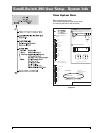
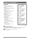
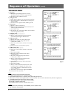
SYSTEM TEST
FAST XFR NO
MORE TEST LOAD XFR
NOTICE
A periodic test of the transfer switch under load conditions is recommended to insure proper operation.
(See National Electric Code articles 700 and 701)