


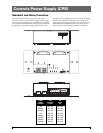
20 GE Zenith Controls
■
ZBTS / ZBTSD Operation and Maintenance Manual (71R-4000A)
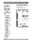
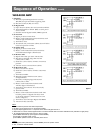
Sequence of Operation
Standard Transition
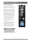
Source 1 Power Failure:
When Source 1 voltage or frequency has fallen below
the preset "Fail" values, the controller initiates the Time
Delay Source 2 Start Timer (Engine Start Timer "P")
cycle. Upon completion of the (P) time delay, an
Engine start Signal is sent to Source 2. When Source 2
voltage and frequency reach the preset "Restore" Values,
the time delay to Source 2 Timer (W) begins its timing
cycle to ensure voltage and frequency stabilization
before transfer. A manual pushbutton BYPASS is provid-
ed to bypass the "W" time delay if desired. After the (W)
time delay, the MX controller initiates a transfer signal
through the SCR-E to operate the main transfer opera-
tor. The load is now transferred to Source 2 line. The
transfer switch is mechanically locked. SN limit switch
awaits the next operation to Source 1.
Restoration of Source 1 Power:
When Source 1 power reach the preset "Restore" values,
the controller initiates re-transfer to Source
1sequence.The delay to Source 1 Timer (T) begins its
timing cycle to ensure voltage and frequency stabiliza-
tion before retransfer. A manual pushbutton BYPASS is
provided to bypass the "T" time delay if desired. After
the (T) time delay, the MX controller initiates a transfer
signal through the SCR-N to operate the main transfer
operator. The load is now transferred to Source 1 line.
The transfer switch is mechanically locked. SE limit
switch awaits the next operation to Source 2.
Immediately after re-transfer, the S2 Stop Delay Timer
(Delay to Engine Stop "U") begins its cycle to allow
Source 2 Engine to run unloaded. A manual pushbut-
ton BYPASS is provided to bypass the "U" time delay if
desired. Upon completion of the (U) timing cycle, the
controller sends an Engine stop signal.
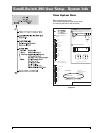
Delayed Transition
Source 1 Power Failure:
When Source 1 voltage or frequency has fallen below the
preset "Fail" values, the controller initiates the Time Delay
Source 2 Start (Engine Start Timer "P") cycle. Upon
completion of the (P) time delay, an Engine start Signal
is sent to Source 2. When Source 2 voltage and frequency
reach the preset "Restore" values, the time delay to open
Source 1 timer (W) begins its timing cycle to ensure
voltage and frequency stabilization before re-transfer. A
manual pushbutton BYPASS is provided to bypass the
"W" time delay if desired. After the (W) time delay, the
MX controller initiates a transfer signal through the
SCR-NO to operate the main transfer operator. The
load is now transferred to the Open position. The time
delay to Source 2 timer (DW) begins its timing cycle.
After the (DW) time delay, the MX controller initiates a
transfer signal through the SCR-E to operate the main
transfer operator. The load is now transferred to Source
2 line. The transfer switch is mechanically locked. SN
limit switch awaits the next operation to Source 1.
Restoration of Source 1 Power:
When Source 1 power reach the preset "Restore" values,
the controller initiates re-transfer to Source 1 sequence.
The delay to open Source 2 Timer (T) begins its timing
cycle to ensure voltage and frequency stabilization
before retransfer. A manual pushbutton BYPASS is pro-
vided to bypass the "T" time delay if desired. After the
(T) time delay, the MX controller initiates a transfer sig-
nal through the SCR-EO to operate the main transfer
operator. The load is now transferred to the Open position.
The time delay to Source 1 timer (DT) begins its timing
cycle. After the (DT) time delay, the MX controller initiates
a transfer signal through the SCR-N to operate the main
transfer operator. The load is now transferred to Source
1 line. The transfer switch is mechanically locked. SE
limit switch awaits the next operation to Source 2.
Immediately after re-transfer, the S2 Stop Delay Timer
(Delay to Engine Stop "U") begins its cycle to allow
Source 2 Engine to run unloaded. A manual pushbut-
ton BYPASS is provided to bypass the "U" time delay if
desired. Upon completion of the (U) timing cycle, the
controller sends an Engine stop signal.
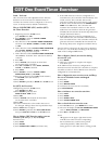
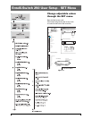
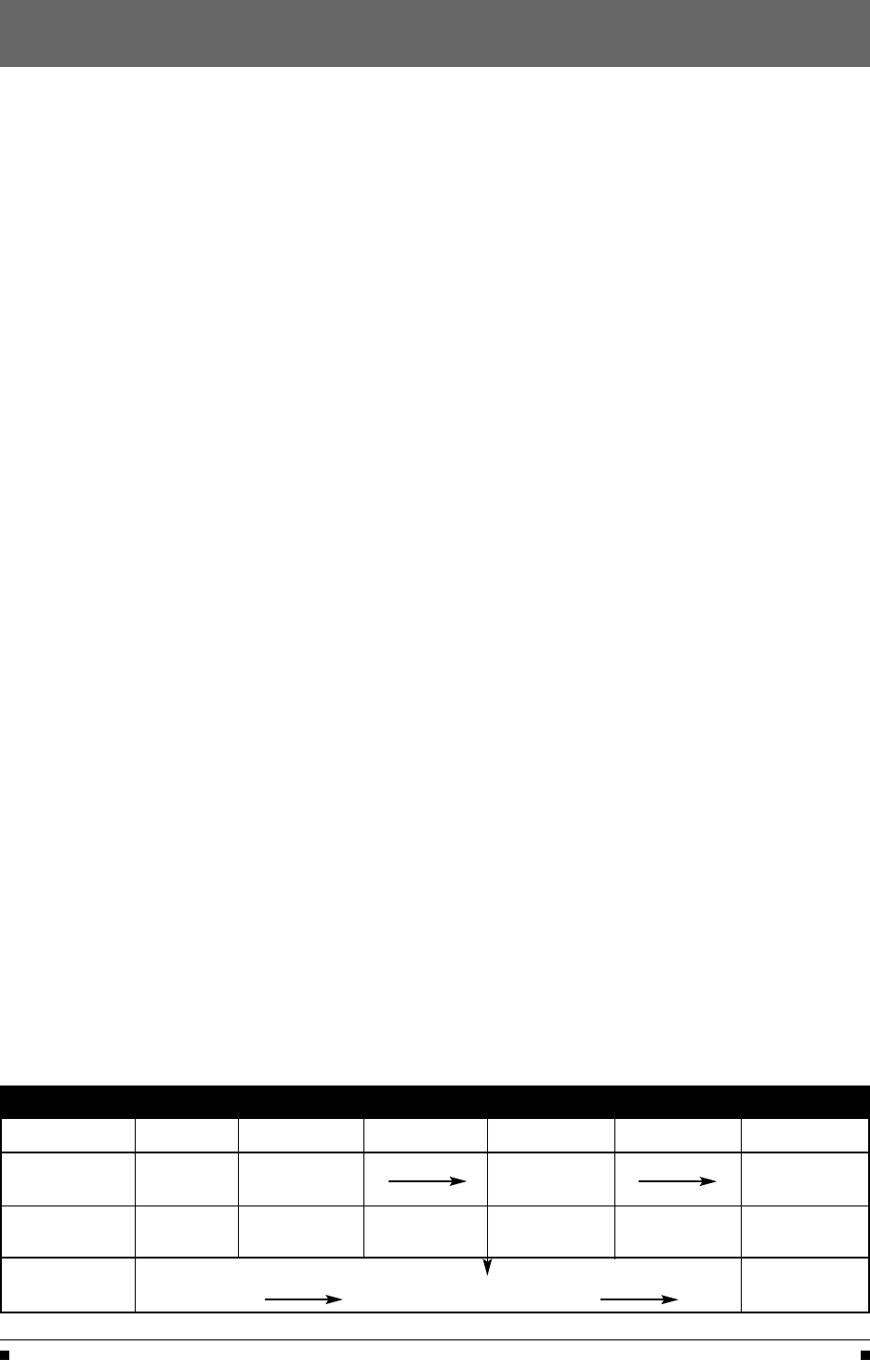
Timer Designations as they appear in the SET menu
ATS Type P W DW T DT U
Standard Time Delay Time Delay Time Delay S2 Stop
Transition S2 Start S2 Stable S1 Stable Delay
Delayed Time Delay Time Delay ATS Open Time Delay ATS Open S2 Stop
Transition S2 Start S2 Stable Time to S2 S1 Stable Time to S1 Delay
Source 1 Transfer to Source 2
Source 1
Transfer to Source 1 Engine
Fails
Returns
Cooldown
Table 4