


page | 4
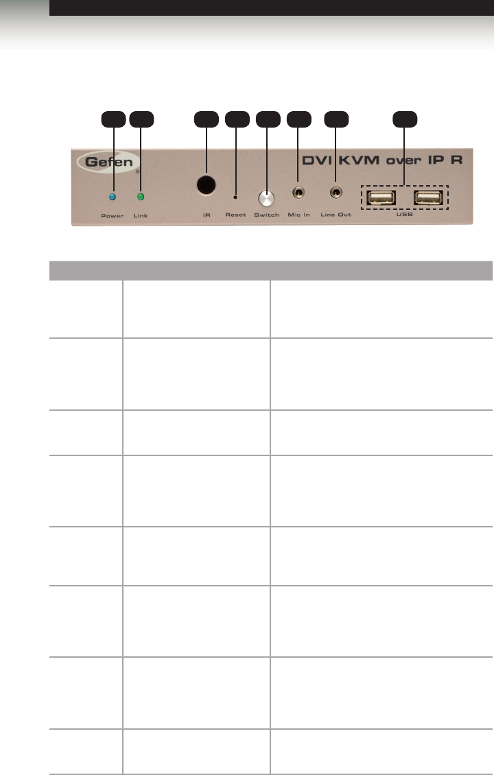
Front
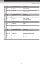
ID Name Description
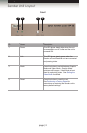
1 Power This LED glows steady blue when the unit
is connected to an AC outlet and the unit is
powered ON.
2 Link This LED glows steady green when the
Sender and Receiver units are connected
using Ethernet cable and successfully
passing video.
3 IR This IR sensor receives signals from the
source IR remote control.
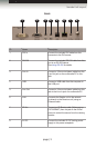
4 Reset Press this button to reset the unit.
See Performing a Factory Reset for
instructions on restoring the Receiver unit to
factory-default settings.
5 Switch Switches the video channel when using
multiple Receiver units on a network.
See Setting the Video Channel for details.
6 Mic In Connect a microphone to this jack. If the
microphone has a 1/4” jack, use a 1/4”-to-
3.5mm adapter to connect the microphone
to the Receiver unit.
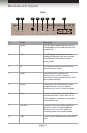
7 Line Out Connect a 3.5mm mini-stereo cable from
this jack to a pair of powered speakers.
See Audio Connections for details on
connecting audio source and speakers.
8 USB Connect up two USB devices to these USB
ports.
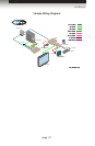
Getting Started
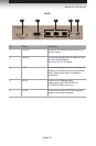
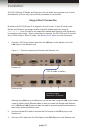
Receiver Unit Layout
1 2
3 4 5 76 8