


2 Generac
®
Power Systems, Inc.
Section 1 — General Information
Generac “V” Type and “Y” Type Transfer Switch
1.1 INTRODUCTION
This manual has been prepared especially for the
purpose of familiarizing personnel with the design,
application, installation, operation and servicing of
the applicable equipment. Read the manual carefully
and comply with all instructions. This will help to
prevent accidents or damage to equipment that might
otherwise be caused by carelessness, incorrect appli-
cation, or improper procedures.
Every effort has been expended to make sure that the
contents of this manual are both accurate and cur-
rent. Generac, however, reserves the right to change,
alter or otherwise improve the product at any time
without prior notice.
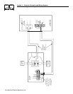
1.2 EQUIPMENT DESCRIPTION
The pre-packaged transfer switch is designed to use
with pre-packaged standby generator control panels.
It is used for transferring critical electrical loads from
a NORMAL (utility) power source to a STANDBY
(emergency generator) power source. Such a transfer
of loads occurs automatically when the NORMAL
power source fails or is subsequently reduced and
the STANDBY source voltage and frequency have
reached an acceptable level. The transfer switch pre-
vents electrical feedback between two different power
sources (such as the NORMAL and STANDBY
sources) and, for that reason, codes require it in all
standby electric system installations.
Once the transfer is completed, the STANDBY power
source then powers electrical loads connected to the
transfer switch. When NORMAL source voltage above
an acceptable (preset) level has been restored, circuit
board action in the pre-packaged control panel initi-
ates re-transfer back to NORMAL power source. After
this re-transfer, the circuit board signals to open the
start circuit to the generator, which shuts down the
engine. The circuit board is then "armed" and ready
for the next drop in NORMAL source voltage.
NOTE:
Keep in mind the pre-packaged transfer switch is
without any kind of electronic controls. It receives
signals solely from circuit boards contained in the
prepackaged control panel.
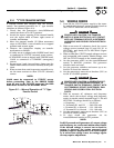
1.3 TRANSFER SWITCH DATA PLATE
Affixed permanently to the transfer switch door is a
DATA PLATE. Use the transfer switch only within the
specific limits shown on the DATA PLATE and on
other decals and labels that may be affixed to the
switch. This prevents damage to equipment, possible
injury to personnel, and provides long and trouble-
free life for the equipment.
When requesting information or ordering parts for
this equipment, make sure to include all information
from the DATA PLATE.
When requesting information or ordering parts for this
equipment, make sure to include all information from
the DATA PLATE.
Record your Model and Serial numbers in the space
provided below for future reference.
1.4 TRANSFER SWITCH ENCLOSURE
The standard switch enclosure is a National
Electrical Manufacturer's Association (NEMA) 1 type.
NEMA 1 type enclosures primarily provide protection
against contact with the enclosed equipment and
against a limited amount of falling dirt.
1.5 SAFE USE OF TRANSFER SWITCH
Before installing, operating or servicing this equip-
ment, read the SAFETY RULES (inside front cover)
carefully. Comply strictly with all SAFETY RULES to
prevent accidents and/or damage to the equipment.
Generac recommends you make a copy of the SAFE-
TY RULES and post them near the transfer switch.
Also, be sure to read all instructions and information
you may find on tags, labels and decals affixed to the
equipment.
Two publications that outline the safe use of transfer
switches are the following:
• National Electrical Code
• UL 1008, STANDARD FOR SAFETY-AUTOMATIC
TRANSFER SWITCHES
MODEL #
SERIAL #