


4 Generac
®
Power Systems, Inc.
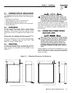
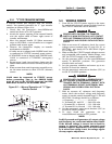
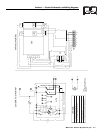
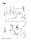
2.4.1 2-POLE MECHANISMS
These switches (Figures 2.2 and 2.3) are used with a
single phase system, when the single phase NEU-
TRAL line is to be connected to a Neutral Lug and is
not to be switched.
Figure 2.2 — 100 Amp 2-pole Transfer
Mechanism
Figure 2.3 — 200 Amp 2-pole Transfer
Mechanism
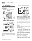
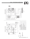
2.4.2 3-POLE MECHANISMS
This switch (Figure 2.4) is also used with a single
phase system, when the single phase NEUTRAL line
is to be connected to a Neutral Lug and is not to be
switched.
Figure 2.4 — 3-Pole Transfer Mechanism
Solderless, screw-type terminal lugs are standard.
Conductor sizes must be adequate to handle the max-
imum current to which they will be subjected; based
on the 75°C column of tables, charts, etc. used to size
conductors. The installation must comply fully with
all applicable codes, standards and regulations.
Before connecting wiring cables to terminals, remove
any surface oxides from the cable ends with a wire
brush. If ALUMINUM conductors are used, apply cor-
rosion inhibitor to conductors. After tightening ter-
minal lugs, carefully wipe away any excess corrosion
inhibitor.
All power cables should enter the switch next to
transfer mechanism terminals. Standard terminal
lugs on the transfer mechanism are solderless,
screw-type.
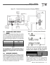
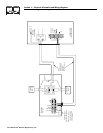
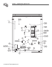
Connect power source load conductors to clearly
marked transfer mechanism terminal lugs as follows
(Figure 2.5 on page 5):
1. Connect NORMAL (utility) power source cables to
switch terminals N1, N2, N3, etc.
2. Connect STANDBY source power cables to trans-
fer switch terminals E1, E2, E3, etc.
3. Connect customer LOAD leads to switch termi-
nals T1, T2, T3, etc.
Conductors must be properly supported, of approved
insulative qualities, protected by approved conduit,
and of the correct wire gauge size in accordance with
applicable codes.
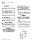
Tighten terminal lugs to the following torques:
100 Amp Switch: 50 INCH-POUNDS
200 Amp Switch: 250 INCH-POUNDS
Make sure to maintain proper electrical 1/2-inch
clearance between live metal parts and grounded
metal.
◆
Section2—Installation
Generac “V” Type and “Y” Type Transfer Switch