


Generac
®
Power Systems, Inc. 3
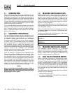
2.1 INTRODUCTION TO INSTALLATION
This equipment has been wired and tested at the fac-
tory. Installing the switch includes the following pro-
cedures:
• Mounting the enclosure.
• Connecting power source and load leads.
• Connecting the generator start circuit.
• Installing/connecting any options and accessories.
• Testing functions.
2.2 UNPACKING
Carefully unpack the transfer switch. Inspect closely
for any damage that might have occurred during
shipment. The purchaser must file with the carrier
any claims for loss or damage incurred while in tran-
sit.
Check that all packing material is completely
removed from the switch prior to installation.
Attach any lifting device to the transfer switch mount-
ing holes or brackets only. DO NOT LIFT THE
SWITCH AT ANY OTHER POINT.
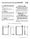
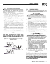
2.3 MOUNTING
Transfer switch components are generally mounted
in a standard NEMA 1 type enclosure (Figure 2.1).
Other options are available such as NEMA 34 and
NEMA 12.
Handle transfer switches carefully when
installing. Do not drop the switch. Protect the
switch against impact at all times, and against
construction grit and metal chips. Never install
a transfer switch that has been damaged.
Install the transfer switch as close as possible to the
electrical loads that are to be connected to it. To pre-
vent switch distortion, level all mounting points. If
necessary, use washers behind mounting holes to
level the unit.
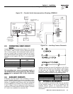
2.4 CONNECTING POWER SOURCE
AND LOAD LINES
Make sure to turn OFF both the normal (Utility)
and standby (generator) power supplies before
trying to connect power source and load lines
to the transfer switch. Supply voltages are
extremely high and dangerous. Contact with
such high voltage power supply lines causes
extremely hazardous, possibly lethal, electrical
shock.
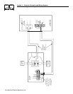
Wiring diagrams and electrical schematics are pro-
vided in this manual. Power source and load connec-
tions are made at a transfer mechanism, inside the
switch enclosure.
DANGER
!
Section2—Installation
Generac “V” Type and “Y” Type Transfer Switch
7.
09
14.
32
6
.7
2
1
9
.
3
7
2
0
.
59
1.1
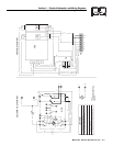
MOUNTING DIMENSIONS - 100 AMP
,
2-POLE UNI
T
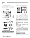
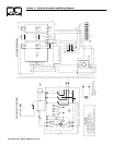
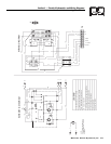
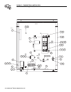
Figure 2.1 — Mounting Dimensions for Enclosures
1
9
.
92
1
5
.
62
24.
07
2
5
.
0
7
7.
63
2.12
M
OU
NTIN
G
DIMEN
S
I
O
N
S
- 2
00
& 4
00
AMP
U
NIT
S