


Generac
®
Power Systems, Inc. 7
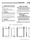
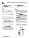
3.3.1 “Y” TYPE TRANSFER SWITCHES
A manual handle was shipped with the transfer
switch. Test manual operation for “Y” type transfer
switches as follows (Figure 3.2):
1. Check that the generator's Auto/Off/Manual
switch has been set to OFF position.
2. Attach the square opening of the manual handle
over the square shaft at lower right corner of
transfer mechanism.
3. Move the manual handle UP. When movement
stops at NEUTRAL, return handle to its original
position and actuate again.
4. Observe the changeover display on transfer
mechanism as follows:
• If utility arrow is aligned with GREEN band, load
is connected to UTILITY (normal) power source.
• If STANDBY arrow is aligned with GREEN band,
LOAD is connected to STANDBY (emergency)
source.
5. Repeat steps 3 and 4 several times, being sure the
switch main contacts actuate normally to all posi-
tions.
6. When certain that switch operates normally, actu-
ate the main contacts to their UTILITY (normal)
source.
NOTE:
LOAD must be connected to UTILITY source
before proceeding. That is, the GREEN BAND
must be next to the UTILITY arrow and the RED
band must be next to the STANDBY arrow.
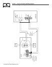
Figure 3.2 — Manual Operation of “Y” Type
Transfer Switch
3.4 VOLTAGE CHECKS
1. Turn ON the UTILITY power supply to the trans-
fer switch with whatever means provided (such as
the UTILITY maim line circuit breaker).
PROCEED WITH CAUTION. THE TRANSFER
SWITCH IS NOW ELECTRICALLY HOT. CONTACT
WITH LIVE TERMINALS RESULTS IN EXTREMELY
HAZARDOUS AND POSSIBLY FATAL ELECTRICAL
SHOCK.
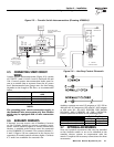
2. With an accurate AC voltmeter, check for correct
voltage across terminal lugs N1 and N2; N1 to
NEUTRAL; and finally N2 to NEUTRAL (Figure
2.5 on Page 5).
3. When certain that UTILITY supply voltage is correct
and compatible with transfer switch ratings, turn
OFF the UTILITY supply to the transfer switch.
4. On the generator panel, set the Auto/Off/Manual
switch to MANUAL position. The generator
should crank and start.
5. Let the generator stabilize and warm up at no-
load for at least five minutes.
6. Set the generator's main circuit breaker (CBI ) to
its ON or CLOSED position.
PROCEED WITH CAUTION. A GENERATOR OUT-
PUT VOLTAGE IS NOW BEING DELIVERED TO
TRANSFER SWITCH TERMINALS. CONTACT WITH
LIVE TERMINALS RESULTS IN EXTREMELY DAN-
GEROUS AND POSSIBLY FATAL ELECTRICAL
SHOCK.
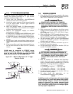
7. With an accurate AC voltmeter and frequency
meter, check the no-load, voltage and frequency
meter at transfer switch terminal lugs E1, E2 and
NEUTRAL. Readings should be as follows:
a. Frequency ........................61-63 Hz
b. Terminals E1 and E2 ......242-253 volts
c. Terminal E1 to Neutral ....121-126 volts
d. Terminal E2 to Neutral ....121-126 volts
8. Set the generator's main circuit breaker (CBI ) to
its OFF or OPEN position.
9. To shut down the generator, set its
Auto/Off/Manual switch to OFF position.
NOTE:
Do NOT proceed until generator AC output voltage
and frequency are correct and within stated limits.
If the no-load voltage is correct but no-load fre-
quency is incorrect, the engine governed speed
probably requires adjustment. If no-load frequen-
cy is correct but voltage is not, the voltage regula-
tor may require adjustment.
DANGER
DANGER
◆
Section 3 — Operation
Generac “V” Type and “Y” Type Transfer Switch