


Generac
®
Power Systems, Inc. 5
Section2—Installation
Generac “V” Type and “Y” Type Transfer Switch
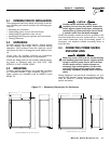
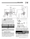
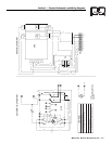
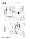
2.5 CONNECTING START CIRCUIT
WIRES
Control system interconnections (Figure 2.5) consist
of UTILITY 1 and 2, LOAD 1 and 2; and leads 23 and
194. Control system interconnection leads must be
run in a conduit that is separate from the AC power
lead. Recommended wire gauge sizes for this wiring
depends on the length of the wire, as recommended
below:
NOTE:
The preceding start circuit connections apply to
the standard 2-wire start system only Your transfer
switch may be equipped with a 3-wire connection
system.
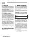
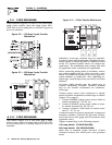
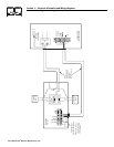
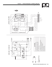
2.6 AUXILIARY CONTACTS
If desired, you can access a set of Auxiliary Contacts
on the Transfer Switch to operate customer acces-
sories, remote advisory lights, or remote annunciator
devices. A suitable power source must be connected
to the COMMON (C) terminal. The contacts labeled 1,
2 and 3 (Figure 2.6) are connected at the factory for
operation of transfer switch advisory lights. Contacts
4, 5 and 6 are available for customer use.
Figure 2.6 — Auxiliary Contact Schematic
Auxiliary contacts are rated 15 amperes at 125, 250 or
480 volts AC; 0.5 ampere at 125 volts DC; 0.25 ampere
at 250 volts DC. DO NOT EXCEED THE RATED
VOLTAGE AND CURRENT OF THE CONTACTS.
Contact operation is shown in the following chart:
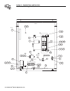
2.7 OPTIONAL ACCESSORIES
Note any optional accessories that may be installed
on the transfer switch or are to be installed in the
standby electric system in conjunction with the
switch. Complete the necessary connections for these
accessories.
MAXIMUM WIRE LENGTH RECOMMENDED WIRE
SIZE
460 feet (140m) No. 18 AWG.
461 to 730 feet (223m) No. 16 AWG.
731 to 1,160 feet (354m) No. 14 AWG.
1,161 to 1,850 feet (565m) No. 12 AWG.
-
O
PEN
S
WIT
C
H T
O
TE
S
T
-
2A
@
2
50
Vac MIN
.
SWITCH TYPE
,
SPS
T
ELECTRICAL RATINGS
,
U
TILITY
1
U
TILITY
2
L
O
AD
2
2
3
1
94
C
B
2
NE
U
TRA
L
CO
NNE
C
TI
ON
N1 N2 N3
E1 E2 E3
NE
U
TRA
L
L
UG
TRAN
S
FE
R
S
WIT
CH
U
TILIT
Y
SU
PPL
Y
L
O
A
D
CUS
T
O
ME
R
19
4
23
LO
AD 2
U
TILITY 2
U
TILITY 1
A
C
G
ENERAT
OR
CO
NTR
O
L PANE
L
N
O
TE
:
P
O
WER LEAD
S
AND
TRAN
S
FER
S
WIT
CH
LEAD
S
M
US
T B
E
R
U
N IN TW
O
DIFFERENT
CO
ND
U
IT
S.
00
E1
E2
E
3
N3
,
E3 AND T3 NO
T
US
ED
O
N
S
IN
G
LE PHA
SE
S
Y
S
TEM
S
LO
AD 1
REMOTE TES
T
SWITCH
(
OPTIONAL
)
Figure 2.5 — Transfer Switch Interconnections (Drawing #79963-B)
Switch Position
Utility Standby
Common (4) to Normally Closed (6) Closed Open
Common (4) to Normally Closed (5) Open Closed