


6 Generac
®
Power Systems, Inc.
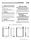
3.1 FUNCTIONAL TESTS AND
ADJUSTMENTS
Following transfer switch installation and intercon-
nection, inspect the entire installation carefully. A
competent, qualified electrician should make the
inspection.
The installation should comply strictly with all appli-
cable codes, standards, laws and regulations. All
electrical connections must be correct and in compli-
ance with applicable codes and standards.
Make sure the standby generator is ready. This
includes checking engine oil level, coolant level, fuel
supply, batteries and other items specified in the
OWNER'S MANUAL for specific generators.
Complete all functional tests as outlined in the FUNC-
TIONAL TESTS section. Do this before placing the
transfer switch into service.
3.2 FUNCTIONAL TESTS
Following transfer switch installation, the entire
standby electric system should be inspected and test-
ed. Have all necessary adjustments completed at this
time. Functional tests of the transfer switch include
these tests: (a) Manual Operation, (b) Voltage Checks
and (c) Electric Operation.
To avoid damaging the transfer switch, perform
functional tests In the exact order given.
Before proceeding with functional tests, read and be
sure you understand all instructions in this section.
Also, read the instructions and information on tags
and decals affixed to the transfer switch. Note any
options and accessories that might be installed or
provided with the switch and review their operation.
DO NOT ATTEMPT MANUAL OPERATION OF THE
TRANSFER SWITCH UNTIL AFTER ALL POWER
VOLTAGE SUPPLIES TO THE SWITCH HAVE BEEN
TURNED OFF. FAILURE TO TURN OFF POWER
VOLTAGE SUPPLIES MAY RESULT IN DANGER-
OUS AND POSSIBLE FATAL ELECTRICAL SHOCK.
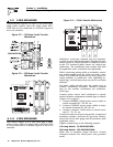
3.3 MANUAL OPERATION
The pre-packaged transfer switch has a choice of two
transfer mechanisms - the "V" type (Model 9227-0)
and the "Y" type (Models 9228, 9229 and 9230).
3.3.1 “V” TYPE TRANSFER SWITCHES
Test manual operation for “V” type transfer switches
as follows:
1. Check that the generator's Auto/Off/Manual
switch has been set to OFF position.
2. Turn OFF the UTILITY power supply to the trans-
fer switch, using whatever means provided (such
as the UTILITY source main line circuit breaker).
3. Set the generator's main circuit breaker to its
OFF or OPEN position.
FAILURE TO TURN OFF ALL A POWER VOLTAGE
SUPPLIES TO THE TRANSFER SWITCH BEFORE
ATTEMPTING MANUAL OPERATION RESULTS IN
EXTREMELY HAZARDOUS AND POSSIBLY FATAL
ELECTRICAL SHOCK.
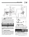
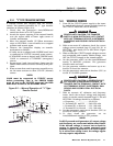
4. Remove the manual transfer handle from the
enclosure.
5. Place open slot of the manual transfer handle on
the small tab of the transfer switch operating
lever (Figure 3.1).
6. Pull manual transfer handle downward, then
move it back to original position. If handle is
down, LOAD is connected to UTILITY power
source. If handle is up, LOAD is connected to
STANDBY power.
7. Move the transfer switch main contacts to both
positions several times. Leave the transfer switch
in the UTILITY position and connect LOAD to the
UTILITY power source (manual operation lever is
up).
Figure 3.1 — Transfer Switch Operation
(“V” Type)
DANGER
◆
DANGER
!
Section 3 — Operation
Generac “V” Type and “Y” Type Transfer Switch