


Maintenance
313872N 29
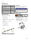
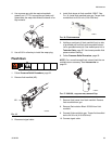
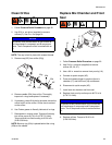
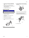
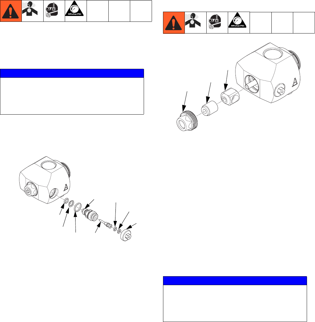
Clean Orifice
1. Follow Pressure Relief Procedure on page 22.
2. Use 5/16 in. nut driver (supplied) to remove
orifices (C). See F
IG. 4 on page 16.
NOTE: The cap is held in place with reverse threads.
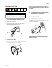
3. Remove cap (25f) from orifice (25g).
4. Remove needle (25h) from orifice. Thoroughly
inspect all o-rings and replace if necessary.
5. If necessary, use drill bit that is the same size as the
orifice to drill out the orifice. Orifice size is marked
on the orifice.
6. Use Fusion grease to liberally lubricate all o-rings.
7. Reassemble in reverse order. Torque orifice body
into orifice cap to 60-70 in-lb (6.78-7.91 N•m).
Torque orifices into fluid housing to 20-30 in-lb
(2.26-3.39 N•m).
NOTE: Back-up ring (25e) is placed behind the o-ring
(25d) on the needle.
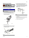
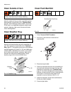
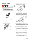
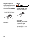
Replace Mix Chamber and Front
Seal
1. Follow Pressure Relief Procedure on page 22.
2. Use 5/16 in. nut driver (supplied) to remove
orifices (25, 26, 27).
3. Use a 3/4 in. wrench to remove front pour tip (19).
4. Connect air quick coupler (AC).
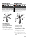
5. Press and release trigger to push out the mix
chamber (17) and front seal (18) and discard.
6. Disconnect air quick coupler (AC).
7. Install new mix chamber and front seal.
8. Replace front pour tip and torque to 60-70 in-lb
(6.78-7.91 N•m).
9. Replace orifices. Torque to 20-30 in-lb
(2.26-3.39 N•m).
NOTICE
To prevent cross-contamination of the orifices do
not interchange A component and B component
parts. The A component orifice is marked with an
A.
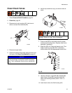
25g
25d
25e
25f
25a
25b
25c
25h
ti19573a
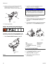
NOTICE
To prevent cross-contamination of the orifices do
not interchange A component and B component
parts. The A component orifice is marked with an
A.
ti19574a
17
18
19