


Repair
32 313872N
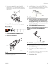
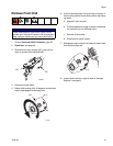
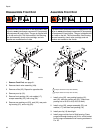
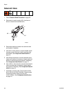
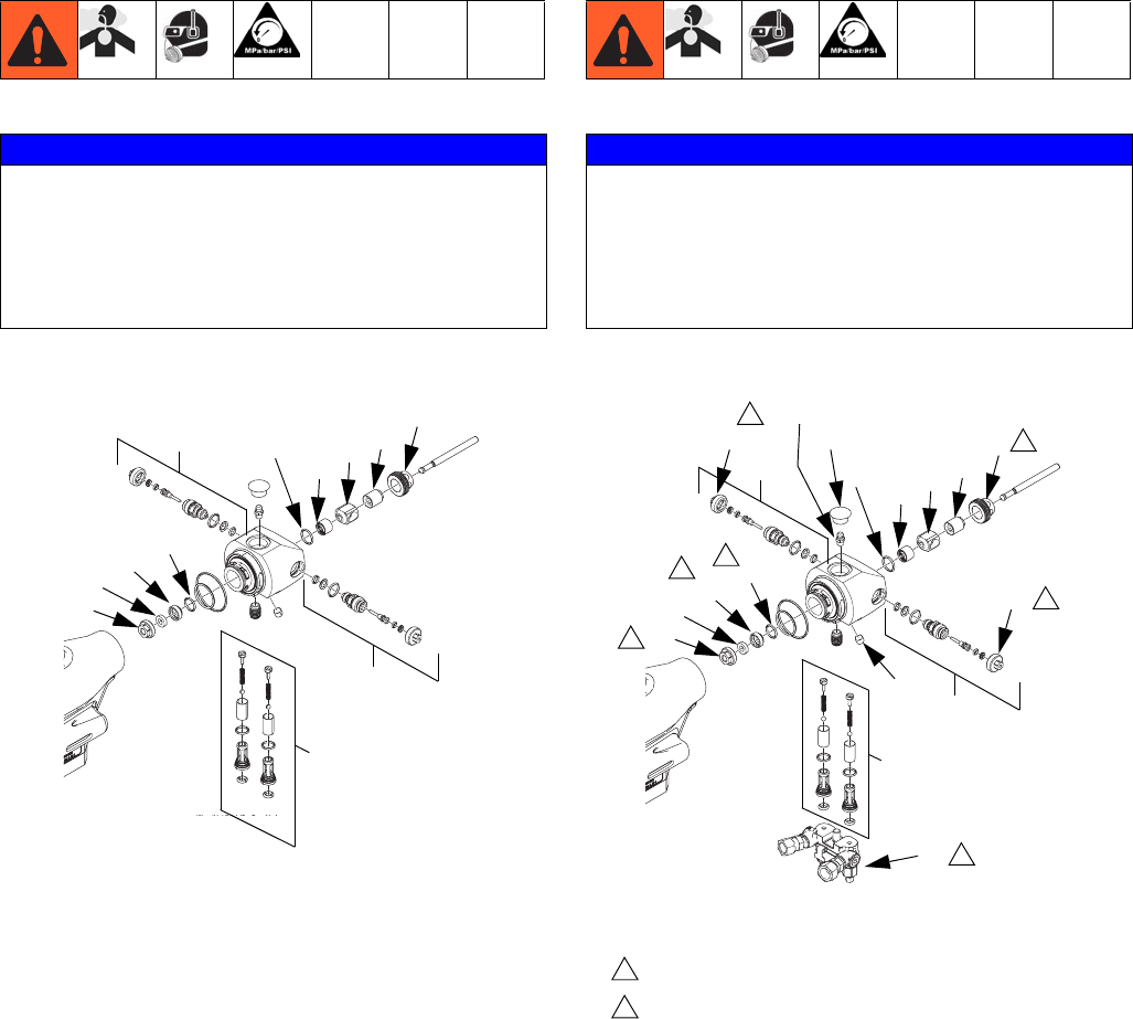
Disassemble Front End
1. Remove Front End, see page 31.
2. Remove check valve assembly (16e).
3. Remove orifice (25). Repeat for opposite side.
4. Remove pour tip (19).
5. Remove front packing (18), mix module (17),
scraper assembly (55), and o-ring (56).
6. Remove rear packing nut (23), seal (22), rear pack-
ing housing (21), and o-ring (20).
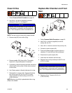
Assemble Front End
1. Install o-ring (20), rear packing housing (21),
seal (22), and rear packing nut (23). Torque rear
packing nut to 20-30 in-lb (2.26-3.39 N•m).
2. Install o-ring (56), scraper assembly (55), mix
module (17), and then front packing (18).
3. Install pour tip (19) hand-tight.
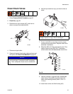
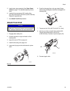
4. Install purge rod into front of fluid housing. Press
purge rod through housing until 3/4 in. of ball socket
end of purge rod extends out of housing as shown in
F
IG. 23.
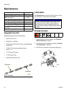
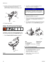
NOTICE
To prevent cross-contamination of the equipment’s wet-
ted parts, never interchange component A (isocyanate)
and component B (resin) parts. The gun is shipped with
the A side on the left. The fluid manifold, fluid housing,
side seal assembly, check valve cartridge, and mix
chamber are marked on the A side.
26
25
17
18
19
16e
20
21
22
23
ti19577a
55
56
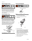
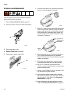
NOTICE
To prevent cross-contamination of the equipment’s wet-
ted parts, never interchange component A (isocyanate)
and component B (resin) parts. The gun is shipped with
the A side on the left. The fluid manifold, fluid housing,
side seal assembly, check valve cartridge, and mix
chamber are marked on the A side.
Torque to 20-30 in-lb (2.26-3.39 N•m)
Torque to 60-70 in-lb (6.78-7.91 N•m)
3
6
ti19578a
26
25
17
18
19
16e
20
21
22
23
3
25a
28
3
3
7
7
3
6
26a
55
56
16c
16b
16t