G-SPEED Product Guide
Pa
e 7
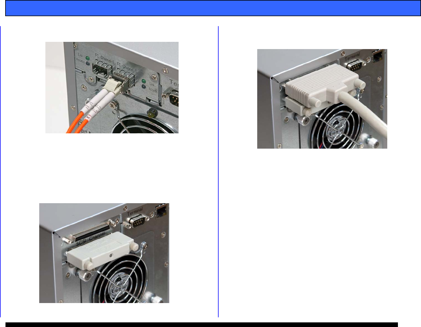
3. Insert the optical cable into the SFP, it will seat with an
audible click.
4. Remove the protective plug from PORT 0 of the SFP
installed in the ATTO HBA and insert the free end of the
optical cable. It will seat with an audible click.
7.4 (SCSI) Installing the SCSI Cable and Terminator
1. Attach the 68pin HD SCSI terminator to the lower SCSI
port on the G-SPEED as shown. Tighten the
thumbscrews to hold the terminator in place.
2. Attach the 68pin HD cable to the upper connector on the
G-SPEED as shown. Tighten the thumbscrews to hold
the cable in place.
3. Attached the other end of the SCSI cable to your
system’s SCSI Host adapter.
7.5 (SCSI) Setting the SCSI ID
1. The G-SPEED is set at the factory with a default SCSI ID
of 0, which is perfect for most applications where there
is only one device connected to your SCSI Adapter. If
you have multiple G-SPEEDs (or other devices)
connected to your system you will need to change the
SCSI ID so all the attached devices have different ID’s.
This setting is modified through the web GUI or the front
panel LCD. See section 8.1 for information on
connecting to the G-SPEED GUI and section 8.2 for
information on changing the SCSI ID via the GUI.
To set the SCSI ID via the front panel LCD, follow the
steps on the next page.


