


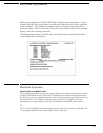

RS-232C
The logic analysis system interfaces with RS-232C communication lines through a
standard 25 pin D connector. The logic analysis system is compatible with RS-232C
protocol. When a hardwire handshake method is used, the Data Terminal Ready
(DTR) line, pin 20 on the connector, is used to signal if space is available for more
data in the logical I/O buffer. Pin outs of the RS-232C connectors are listed in the
following table.
RS-232C Signal Definitions
Pin
Number
Function RS-232C
Standard
Signal Direction and Level
1 Protective Ground AA Not applicable
2 Transmitted Data (TD) BA Data from Mainframe
High = Space = "0" = +12 V
Low = Mark = "1" = –12 V
3 Received Data (RD) BB Data to Mainframe
High = Space = "0" = +3 V to +25 V
Low = Mark = "1" = –3 V to –25 V
4 Request to Send (RTS) CA Signal from Mainframe
High = ON = +12 V
Low = OFF = –12 V
5 Clear to Send (CTS) CB Signal to Mainframe
High = ON = +3 V to +12 V
Low = OFF = –3 V to –25 V
6 Data Set Ready (DSR) CC Signal to Mainframe
High = ON = +3 V to +25 V
Low = OFF = –3 V to –25 V
7 Signal Ground AB Not applicable
8 Data Carrier Detect (DCD) CF Signal to Mainframe
High = ON = +3 V to +25 V
Low = OFF = –3 V to –25 V
20 Data Terminal Ready (DTR) CD Signal from Mainframe
High = ON = +12 V
Low = OFF = –12 V
23 Data Signal Rate Selector CH/CI Signal from Mainframe
Always High = ON = +12 V
8–19