


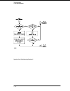
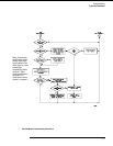
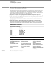
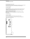
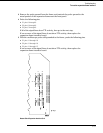
To check the power supply voltages
Refer to chapter 6, "Replacing Assemblies," for instructions to remove or replace covers and
assemblies.
WARNING
Hazard voltages exist on the power supply, the CRT, and the CRT driver board. This
procedure is to be performed by service-trained personnel aware of the hazards involved,
such as fire and electrical shock.
1
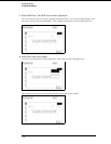
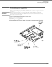
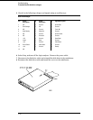
Turn off the instrument, disconnect the power cord, then remove the top cover.
2 Apply power to the instrument.
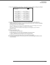
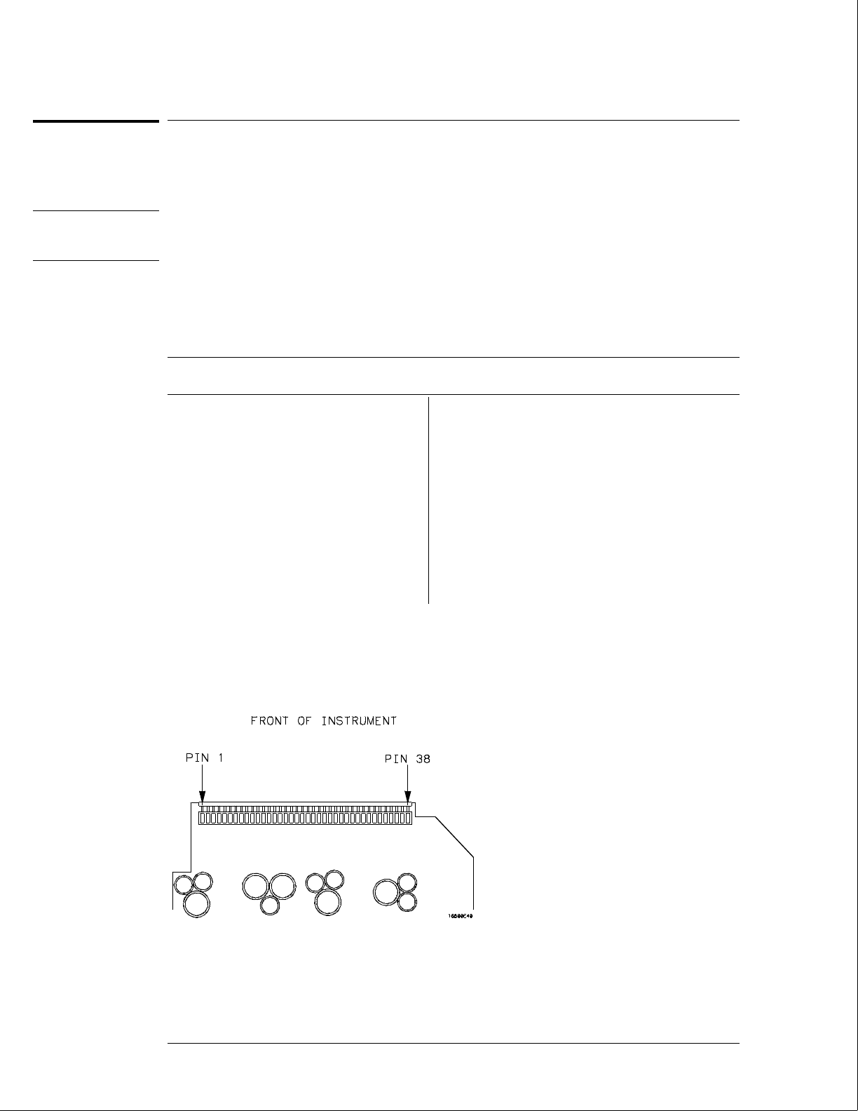
3 Using a DVM, measure the power supply voltages.
4 Note problems with the power supply, then return to the power supply flowchart.
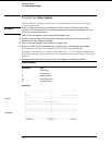
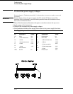
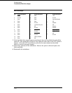
Power Supply Voltages
Pin Supply/Signal Voltage Pin Supply/Signal Voltage
1-5 5 volt +5 V 21 Ground sense 0 V
6 +5 volt remote sense +5 V 22 Power valid +5 V
7-9 +3.5 volt +3.5 V 23
−3.25 volt remote sense −3.25 V
10 +3.5 volt remote sense +3.5 V 24-30
−3.25 volt −3.25 V
11 +12 volt +12 V 31
−5.2 volt current limit
+2.5 V
12
−12 volt −12 V
32
−5.2 volt remote sense −5.2 V
13 Not connected 33-37
−5.2 volt −5.2 V
14-20 Ground 0 V 38 Remote on/off +12 V
Troubleshooting
To check the power supply voltages
5–24