


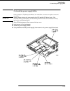
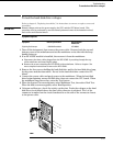
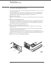

3 Remove the probe ground from the frame, and reattach the probe ground to the
metal portion of the expansion frame near the front panel.
4 Probe the following pins.
•
U1 pins 2 through 9
•
U2 pins 2 through 9
•
U3 pins 5 through 9
If all of the signal lines show TTL activity, then go to the next step.
If one or more of the signal lines do not show TTL activity, then replace the
expansion frame interface board.
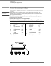
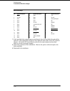
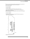
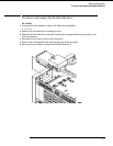
5 With the oscilloscope probe still grounded to the frame, probe the following pins.
•
U1 pins 11 through 18
•
U2 pins 11 through 18
•
U3 pins 11 through 15
If one or more of the signal lines do not show TTL activity, then replace the
expansion frame interface board.
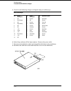
Bottom Side of Expansion Interface Card
Troubleshooting
To test the expansion frame interface
5–31