


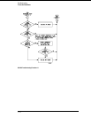
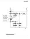
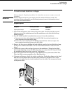
To check the video signals
Refer to chapter 6, "Replacing Assemblies," for instructions on how to remove or replace
covers and assemblies.
WARNING
Hazard voltages exist on the power supply, the CRT, and the CRT driver board. This
procedure is to be performed by service-trained personnel aware of the hazards involved,
such as fire and electrical shock.
1
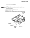
Turn off the instrument, then remove the bottom cover.
2 On the color assembly, disconnect the cable that connects the microprocessor
board to the color display assembly.
3 Turn on the instrument, then wait for it to power up.
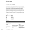
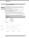
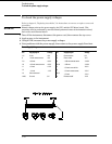
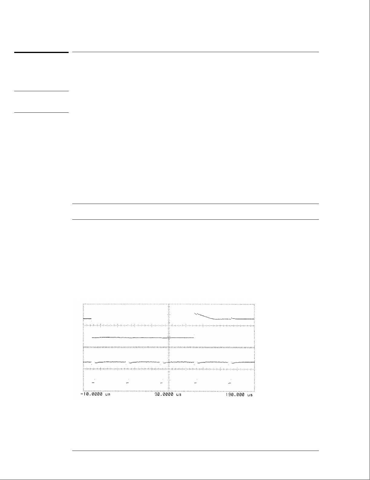
4 Probe the cable for the horizontal sync, vertical sync, and display data signals.
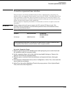
The horizontal and vertical sync signals are TTL levels that resemble the figure.
The display data signals have a baseline of approximately −1.7 V and vary in amplitude from
the baseline voltage to approximately 125 mV, depending on the characteristics of the colors
displayed.
5
Reconnect the cable, then return to the color display assembly flowchart.
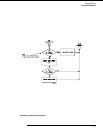
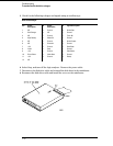
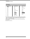
Cable Pin Numbers
Pin Numbers Signal
3 Vertical Sync
7 Horizontal Sync
21 Red Display Data
29 Green Display Data
37 Blue Display Data
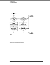
Sync Signals
Vertical
Horizontal
Troubleshooting
To check the video signals
5–22