


2-23
Installing the Switch
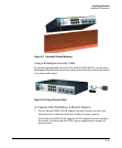
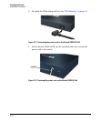
Sample Network Topologies
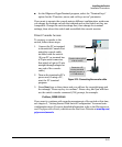
As shown in the above illustration, the IP telephones can be connected in line,
that is, between the switch and the end device, in this case a PC. The IP
telephones have two ports, one in and one out. Therefore the phone receives
voice and power from the switch and the PC can send and receive data through
the phone to the switch.
The end node devices are connected to the switch by straight-through or
crossover twisted-pair cables. Either cable type can be used because of the
Auto-MDIX feature on the 2520G-PoE switches.
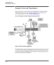
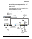
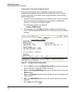
As a Segment Switch Implementing PoE
Figure 2-17. Segment network configuration with PoE switches
Server
Switch 2510G-24
Gigabit
fiber-optic cable
uplink
Switch 2520G-24-PoE
Switch 2520G-8-PoE
Twisted-pair straight-
through or crossover cables
Gigabit
fiber-optic cable
uplink