


67
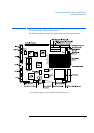
3 System Board (P/Ns D3657-63001 and D3661-63001)
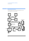
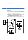
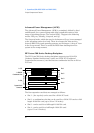
Principal Components and Features
Processor Socket
The microprocessor is packaged in a pin-grid-array (PGA), which is seated on
the system board in a Zero-Insertion-Force (ZIF) socket.
VRM Socket
P54CS (133 150 and 200 MHz) Pentium processors require a 3.3V supply. Since
the PC has a regulated 3.3 V output, a shorting block is used to connect the
output directly to the processor.
The P54C 166 MHz Pentium processor requires slightly more than 3.3 V and
therefore needs an active VRE voltage regulator module (VRM), in which the
voltage is derived from both the 3.3 V and 5 V outlets of the power supply.
Main Memory Sockets
There are six main memory module sockets, arranged in three banks (A to C),
allowing installation of up to 128 MB DRAM.
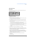
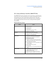
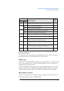
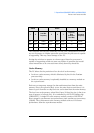
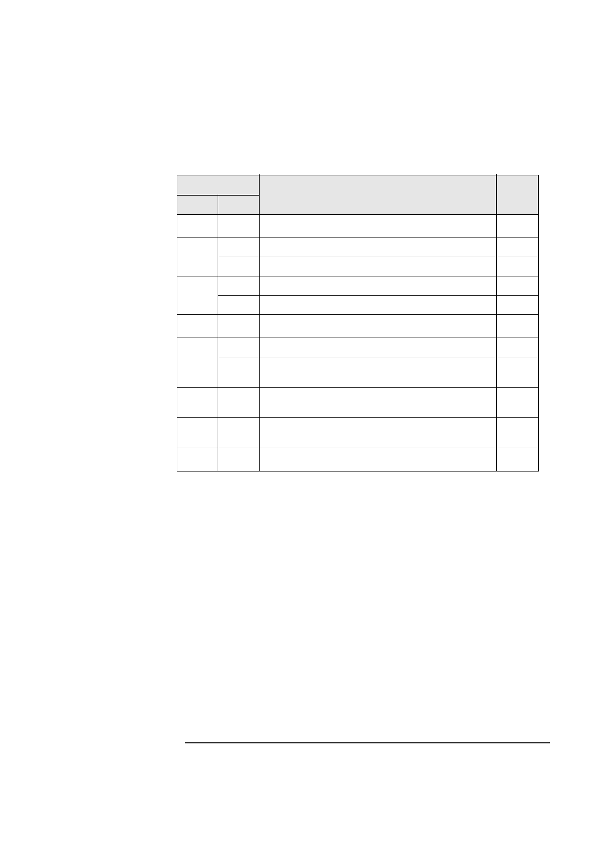
Switch Functions
Default
Setting
Switch Setting
1 - 4
- Selects system board speed settings, refer to “Bus Frequencies” on page 72.
5
Open Enables User and Administrator passwords. Open
Closed Clears User and Administrator passwords.
6
Open CMOS memory acts as a non-volatile store for the Setup program.. Open
Closed Clears the Setup configuration data in the CMOS memory.
7
Selects system board speed settings, refer to “Bus Frequencies” on page 72.
8
Open Disables secure mode. Open
Closed Sets the security mode. Sets the switch to the closed position to prevent the
BIOS from being upgraded and to disable writing to disks.
9
Open Disables space-bar power-on. This setting overrides the setting in the Setup
program.
Open
Closed Enables space-bar power-on. If you want to enable this feature, set this switch
to Closed. This setting overrides the setting in the Setup program.
10
Not used.