


Output Connections and Operating Information44
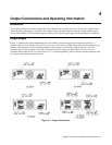
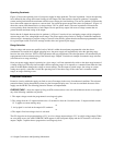
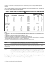
Operating Quadrants
Figure 4-2 shows the operating locus of your power supply in three quadrants. The area in quadrant 1 shows the operating
locus defined by the voltage and current settings of each output. The characteristics shown for quadrant 1 incorporate
remote sensing and include the maximum available sense voltage plus load lead drop. The area in quadrant 2 indicates the
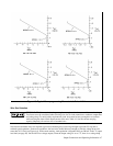
locus where each output can operate as a current sink. You cannot program current limit values in quadrant 2. (Figure 4-3
shows the current sink characteristics at voltages below 2.0 V in greater detail.) The area in quadrant 4 illustrates the
reverse polarity diode characteristics of each output. Do not operate any output with reverse-voltage currents that are
greater than the maximum rating of the output.
Notice that the L shaped characteristics in quadrant 1 of Figure l-l consists of two overlapping ranges-a high voltage/low
current range, and a low voltage/high current range. The power supply always limits its settings to within the boundaries
of these ranges. Attempting to program voltage or current values that are greater than the maximum programmable values
for a given output results in an error message and the values are ignored by the supply.
Range Selection
When a voltage and current are specified, each of which is within the maximum programmable value but whose
combination lies outside the L shaped operating locus, the power supply will automatically select the operating range
based on the value of the last VSET or ISET parameter that was programmed. The other parameter will automatically be
reprogrammed to the maximum rating of the selected range. Chapter 5 includes an example of automatic range selection
(also referred to as range switching).
Once your power supply output is operating in a given range, it will not automatically switch to the other range because of
a change in the load. The only time an output switches operating ranges is in response to a command from either the front
panel or the HP-IB that changes the voltage or current settings. For the output to switch ranges, the voltage or current
setting must specify a value that is inside the operating locus of the other range. If the value sent is common to both
ranges, no range switching occurs.
Protection Features
Protective circuitry within the supply can limit or turn off an output in the event of an abnormal condition. The activated
protection feature can be determined by observing the front panel display area. You can also read back the status of the
supply over the HP-IB. The following protection features are implemented:
OVERVOLTAGE -- shorts the output by firing an SCR crowbar and sets zero volts and minimum current on an output if
any of the following conditions are present:
1. The output voltage exceeds the programmed overvoltage trip point.
or
2. The voltage from the +V output terminal to the + S terminal or from the -S terminal to the -V output terminal exceeds
1.5 V (applies to remote sensing only).
or
3. A trip signal is received on the output's OV terminals.
or
4. The output's fixed overvoltage circuit is activated.
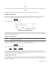
The OV trip point can be programmed up to 23 V on a low voltage output and up to 55 V on a high voltage output. When
an overvoltage occurs, the word OVERVOLTAGE appears in the front panel display and the OV status bit is set for that
output. Chapter 5 explains how to program the overvoltage trip level.