


Output Connections and Operating Information50
sensing is especially useful for CV operation with load impedances that vary or have significant lead resistance. It has no
effect during CC operation. Because sensing is independent of other power supply functions, remote sensing can be used
regardless of how the power supply is programmed. Note that with remote sensing, voltage readback monitors the load
voltage at the sense points.
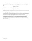
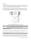
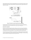
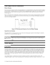
Figure 4-5. Remote Voltage Sensing
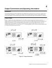
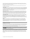
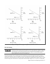
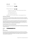
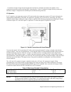
Figure 4-6. Allowable Load Lead Voltage Drop with Remote Sensing
The maximum voltage available at the power supply output terminals during remote sensing (see Figure 4-6) is the
maximum voltage (20.2 V or 50.5 V) rating, plus one volt (i.e. 21.2 V or 51.5 V as shown in Figure 4-2).This allows a
voltage drop of 0.5 V per load lead, or one volt total. For lower output voltages refer to Figure 4-2.
Remote Sense Connections
Remember to turn off the power supply before making or changing any connections on the rear panel terminal blocks.
Connect the unit for remote sensing by first disconnecting the straps between sense and load terminals. Then make your
connections as shown in Figure 4-5. Connect the sense leads as close to the load as possible. See pages 47 & 48 for
information on selection of load lead wire gauge. Best results will be obtained by using the shortest load leads practical. It
is recommended that you keep your load leads under 14.7 meters (50 feet) per lead because of inductance effects.
The sense leads carry only a few milliamperes of current and therefore, can be lighter gauge than the load leads. However,
note that any voltage drop in the sense leads can degrade the voltage regulation of the supply. Try to keep the sense lead
resistance less than about 0.5Ω per lead (this requires 20 AWG or heavier for a 50 foot length). You can use the following
formulas to calculate the CV load regulation error when using remote sensing: