


Output Connections and Operating Information46
A fixed overvoltage threshold of approximately 120% of the maximum rated output voltage is built into each output.
Because the fixed overvoltage circuit is biased from the output terminals, it can be activated and provide protection even
when the supply is not connected to the ac power line.
The OVRST command restores the programmed voltage and current values and clears the OV once the cause of the
overvoltage has been eliminated.
OVERCURRENT--when the overcurrent protection feature is enabled, and the output is sourcing current and enters the
+ CC operating mode, the output will be disabled (set to zero volts and minimum current) and the word OVERCURRENT
will appear on the front panel display. In addition the OC status bit is set for that output. The OCRST command restores
the programmed voltage and current values and clears the OC once the cause of the overcurrent condition has been
eliminated. Refer to Chapter V for programming details.
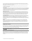
UNREGULATED OUTPUT--the supply informs the user when output regulation is not guaranteed. This can occur
when attempting to sink excessive currents below 2.5 volts or when operating outputs in parallel. The UNR annunciator
on the front panel and the UNR bit in the status register indicate that the specified output is unregulated. Line voltage
dropout or an incorrectly set ac power module can also cause the output to become unregulated. If line voltage dropout
continues, the supply shuts down and will return to the power-up condition when normal line voltage is restored.
OVERTEMPERATURE--shuts down the linear pass and downprogrammer of the output that has reached an unsafe
operating temperature. Operation of the other outputs is unaffected. An overtemperature can occur because of excessively
high ambient temperature, a blocked fan, or insufficient space at the sides for adequate air circulation. When an
overtemperature condition occurs, the word OVERTEMP appears in the front panel display and the OT status bit is set.
This circuit resets automatically and restores the output approximately 30 seconds after the temperature drops sufficiently
for safe operation.
ERROR--if the power supply receives an invalid command either through the front panel or the HP-IB, the ERR
annunciator on the front panel comes on and the ERR bit in the serial poll register is set. The power supply does not
execute the command and remains at previously set values. Pushing the ERR button in local mode displays the error
message and clears the error. The error indicator may also indicate that an instrument failure has occurred. Refer to
Appendix D for further details.
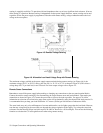
CONNECTING THE LOAD
Each terminal block cover on the rear panel is secured by a locking tab which snaps into a slot at the left of the terminal
block. To remove, insert a screwdriver into this rectangular slot and move the locking tab to the left. When the locking tab
releases, gently pull the terminal block cover away from the terminal block. To reinstall the cover, align it over the
terminal block and gently press it into position until the locking tab engages.
SHOCK HAZARD Turn off ac power before making rear panel connections. All wires and straps
must be properly connected with terminal block screws securely tightened. Replace terminal block
covers before reapplying power.
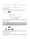
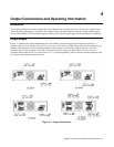
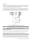
Each rear terminal block has six M3.5 x 0.6 x 6 mm screws for attaching wires (see Figure 2-2). Load connections to the
supply are made at the + V and -V terminals on each terminal block Do. not connect unterminated wires to the load
terminals. Wires used for load connections must be properly terminated with termination connectors securely attached.
Remember to replace the impact resistant plastic covers (HP P/N 06624-20007) over the terminal blocks after making
connections.