


Output Connections and Operating Information 55
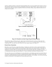
- V terminals of output 1 keeps the total length of the load leads to a minimum and reduces the number of wire
connections that must be made at the load itself. Connecting the + S and - S terminals of output 2 directly to the sense
terminals of output 1 compensates for the IR drop in the interconnecting load leads.
CV Operation
For CV operation, one output must operate in CC mode and the other output must operate in CV mode. Although each
output operates independently of the other, the output that is operating in CV mode will be ''controlling" the voltage
regulation of both outputs. Setting the output voltages as outlined in the following paragraph and configuring the outputs
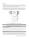
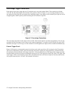
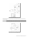
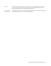
as shown in Figure 4-11 will allow output 1 to operate in CV mode and output 2 to operate in CC mode.
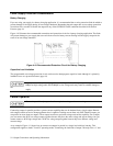
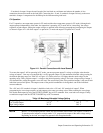
Figure 4-11. Parallel Connections with Local Sensing
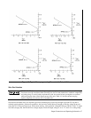
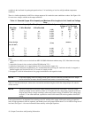
To assure that output 2 will be operating in CC mode, you must program output 2's voltage to a higher value than the
voltage of output 1. One way to accomplish this is to first program output 2 to the maximum allowable voltage setting for
the desired operating range (see Table 4-2 or Figure 4-2). These values are 1% higher than the rated voltage for the
operating range. Then, program output 1's voltage to the desired operating voltage. The lower voltage setting of output 1
will determine the voltage that appears across the load. The current limit point of the paralleled outputs is the sum of both
individual current limit points. The output current of the parallel combination is the algebraic sum of the individual
current readbacks.
The + OV and - OV terminals of output 1 should be wired to the + OV and - OV terminals of output 2. When
programming the overvoltage setpoint, set both outputs to the same overvoltage value. When resetting the overvoltage,
first disable both outputs by using the OUTPUT ON/OFF key or OUT command. Next, reset both overvoltages. Finally,
re-enable the outputs with the OUTPUT ON/OFF key or OUT command.
Table 4-2. Maximum Allowable Voltage Setting
Output Type(40 W & 80 W) Maximum Low Range Voltage Maximum High Range Voltage
Low Voltage Output 7.07 V 20.2 V
High Voltage Output 20.2 V 50.5 V
NOTE Below 2.5 V the downprogrammer cannot sink the maximum rated current. (See Figures 4-2 and 4-3).
To operate parallel outputs at voltages under 2.5 V, program both outputs to the same voltage setting.
Depending on the load, one output may operate in the unregulated mode.