


Remote Operation 75
The Mask and Fault Register. The fault register works in conjunction with the mask register. These are two eight bit
registers which report any fault condition on a particular output channel. The mask register is used to set up the
conditions that generate a fault which is latched into the fault register. The user can then read the fault register to
determine the fault. When a bit in the fault register is set, the power supply can generate a service request for that output
providing the service request command on fault (SRQ 1 or SRQ 3) was previously sent. See page 76 for a discussion on
service request.
To understand how these two registers work, we must include the status register in this discussion. Recall that the status
register takes its input from the power supply and the user cannot change its contents. The mask register takes its inputs
from the user, and the power supply cannot change its contents. The fault register takes its inputs from both the mask and
the status registers. You can find out the setting of the mask register of output 2 by sending the following query and
addressing the supply to talk:
UNMASK? 2
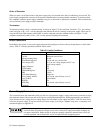
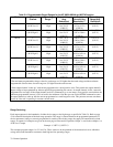
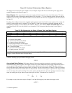
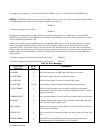
The response will be a numeric code between 0 and 255 which can be decoded by consulting Table 5-5. You can set the
conditions to generate a fault by setting (unmasking) one or more bits in the mask register. The conditions will remain
unmasked until you change them. To unmask conditions in output 2 for example, send the following command:
UNMASK 2,XXX
where XXX specifies the numeric code (0 to 255) for the unmasked conditions (see Table 5-5). If during operation, the
output experiences any of the previously unmasked conditions, it will set the corresponding bit(s) in its fault register.
Remember that the bits in the fault register can be set when there is a change in either the status register or the mask
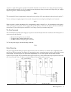
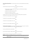
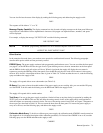
register. Each output has its status, mask, and fault registers arranged as shown in Figure 5-3 and Table 5-5. The mask
register, which is set by the user, is used to specify which bits in the status register are enabled (unmasked) to set bits in
the fault register. A bit is set in the fault register when the corresponding bit in the status register changes from "0'' to "1"
and the corresponding bit in the mask register is a "1". Also, if a bit in the status register is already set and then the
corresponding bit in the mask register is set (unmasked), the corresponding bit in the fault register will be set.
In addition, if both status and mask register bits remain set after the fault register was read (and cleared), the fault register
will remain cleared as long as there are no changes in either the status or mask registers with the following exception.
Executing a VSET, ISET, RCL, OVRST, OCRST, or OUT on/off command, will cause the CV, + CC, - CC, or UNR bit
(as applicable) in the fault register to be set. Note that the fault register is cleared immediately after it is read.
As shown in Figure 5-3, if one or more bits in the fault register of a given output channel are set, then the FAU bit for that
output in the serial poll register will also be set and a service request may be generated (see page 76). To read the fault
register of output 2 and find out which bits are set, send the following query and address the supply to talk:
FAULT? 2
The power supply responds with a number which can be decoded from Table 5-5. For example, the number 9 (8 + 1)
indicates that the OV and the CV bits in the fault register are set.
NOTE If the condition(s) generating the fault(s) is (are) removed but the fault register is not read, the bit(s) in
the fault register will remain set.
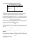
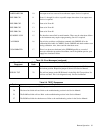
The Serial Poll Register. The serial poll register is an 8 bit register which the supply uses to keep track of its internal
operating status and to determine the operating status of each of its outputs. Table 5-6 defines each bit.
Table 5-6. Bit Assignment of the Serial Poll Register
Bit Position 7 6 5 4 3 2 1 0
Bit Weight 128 64 32 16 8 4 2 1
Meaning PON RQS ERR RDY FAU 4 FAU 3 FAU 2 FAU 1