


Output Connections and Operating Information52
Overvoltage Trigger Connections
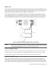
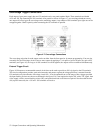
Each output of your power supply has two OV terminals on its rear panel terminal block. These terminals are labeled
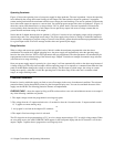
+OV and -OV. By connecting the OV terminals all in parallel as shown in Figure 4-7, an overvoltage shutdown on any
one output will also trigger the overvoltage on the remaining outputs. Any number of OV terminals up to eight sets can be
strapped together. Observe polarity when connecting the OV terminals in parallel.
Figure 4-7. Overvoltage Connections
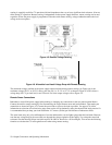
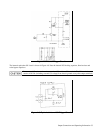
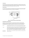
The overvoltage trip point for each output can be set either from the front panel or by remote programming. You can also
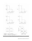
externally fire the overvoltage circuit of one or more outputs by applying a 5 volt pulse of at least 50 µS to any pair of OV
terminals (see Figure 4-8). As long as all OV terminals are wired together, the outputs will be crowbarred simultaneously.
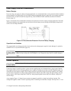
External Trigger Circuit
Figure 4-8 illustrates a recommended external circuit that can be used to provide an OV trip signal to the OV terminals.
This circuit configuration provides good noise immunity and protects against the voltage pulse that is returned from the
OV terminals every time that the overvoltage circuit fires. It can be operated from a wide range of bias voltages provided
the input limiting resistors are chosen as tabulated in the figure. If it is not required to trip the OV with a TTL signal, then
a bias supply, switch, current limiting resistor (R2), and protection diode are all that are required. Note that with the unit
off (ac power removed), the + OV and - OV terminals are inactive.