


Remote Operation68
Order of Execution
When you send a set of instructions to the power supply, they are executed in the order in which they are received. The
power supply completes the execution of the present command before executing another command. To send more than
one command within the power supply command string, use a semicolon to separate the commands. This maximizes the
rate at which the power supply accepts commands.
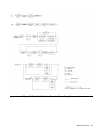
Terminators
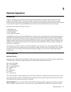
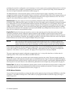
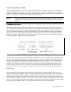
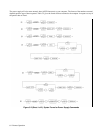
Terminators mark the end of a command string. As shown in Figure 5-2, the semicolon, line feed < LF >, and carriage
return line feed < CR > < LF > are the characters that indicate the end of a message to the power supply. When you are
using the HP Series 200 computer with BASIC to send a command using the standard format (see Figure 5-1), the
computer automatically sends < CR > < LF > on the data bus following the command.
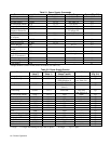
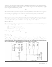
Initial Conditions
Immediately after power on, the power supply automatically undergoes a self-test and sets all parameters to their initial
values. Table 5-3 lists the parameters and their initial values.
Table 5-3. Initial Conditions
Parameter Initial Value
Voltage 0
Current Minimum current limit
Reprogramming Delay 20 mS
Store/Recall Registers 0 volts and min. current limit
Overvoltage (OV) 23 V on low voltage outputs and 55 V on
high voltage outputs
Output Channels On
OCP Enabled Off
UNMASK Register 0 (cleared)
SRQ 0 (Off)
Front Panel Metering Output #1
Power Supply Address Last stored value (Factory set to 5)
Local Control On (enabled)
PON Bit On
PON SRQ Last stored value (Factory set to 0)
Cal Mode Off
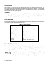
Power Supply Commands
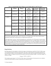
This section discusses the commands which you will use to program the supply's voltage and current, protection circuits,
and enhanced features like storage and recall registers, and reprogramming delay. When programming, you should be
aware that the current, voltage and overvoltage ranges for each output of your supply may differ. Table 5-4 shows these
values for the power supply. If you send values out of these ranges, you will get a number range error. A summary of all
commands appears in Appendix C.
The output voltage of some output channels exceeds the safe operating limit of 42.2 V. To avoid any
electrical shock, program the voltage to zero volts or turn off ac input power before changing any
rear panel connections. Make certain all straps are properly connected, terminal block screws are
securely tightened and terminal block covers are replaced before reapplying power.