


3-3
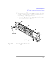
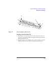
Typical Installation in a VME Card Cage
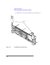
Configuring the VME Card Cage
Configuring the VME Card Cage
This section provides step-by-step instructions for configuring the VME
card cage.
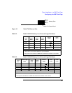
Use Table 3-1 to determine the configuration for the VME card cage.
CAUTION: In the Model 748 card cage, slots 1 and 2 are powered by the bottom power
supply. Slots 3 through 8 are powered by the top power supply. A Model 744
Board Computer with its expansion kit attached, installed in slots 2 and 3, will
cause the power supplies to shut down.
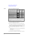
To determine the board computer’s power needs, follow these instructions:
1 Determine the board computer’s current requirements from the Computer
Current Requirements Worksheet (Table 3-4).
Table 3-1 Determining the VME Card Cage Configuration
If your Model 744
Board Computer...
Then...
has an HP A4262A Expansion Kit
attached, and will be installed in an
HP 9000 Series 700 Model 748 VME
System,
the Model 744 Board Computer must
be installed in either:
Slots 1 and 2; the bottom two slots
Slots 3 and 4, or any other higher-
numbered slot pair
See the CAUTION text.
is single-board configured, the VME card can be installed in any
slot.
was removed from its VME card cage
to change or add accessories,
see “Model 744 Installation” on page
3-8.
is going to be installed for the first
time in a VME card cage,
follow the step-by-step instructions
below.