


3-5
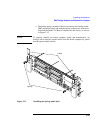
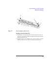
Typical Installation in a VME Card Cage
Configuring the VME Card Cage
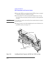
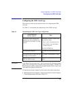
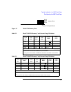
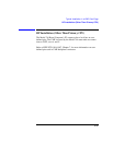
Figure 3-1 Model 744 Memory Slots
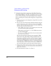
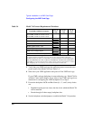
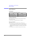
Table 3-2 Model 744/132L Memory Card Current Usage Worksheet
Memory
Card
Size
First
Active
Bank
1
Second
Active
Bank
Third
Active
Bank
Inactive
Banks
Totals
(+5V)
32 MB
2
1.15 A 1.15 A 1.15 A 0.05A x ___ _________
64 MB 2.6 A N/A N/A 0.1 A x
___ _________
128 MB 1.45A N/A N/A 0.07 A x
___ _________
16 MB 1.15 A N/A N/A 0.05A x ___ _________
Total memory current _________
1
Choose the worst case active bank(s) for your calculation.
2
Slot positions and amount of 32MB cards determine the number of active banks.
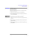
Table 3-3 Model 744/165L Memory Card Current Usage Worksheet
Memory
Card
Size
First Active
Bank
1
Second
Active
Bank
Third
Active
Bank
Inactive
Banks
Totals
(+12V)
Totals
(+5V)
32 MB
2
0.53 A (+12V) 0.53 A 0.53 A 0.023A x ___ _______
64 MB 1.2 A (+12V) N/A N/A 0.05 A x
___ _______
128 MB 1.45 A (+5V) N/A N/A 0.07 A x
___ ______
16 MB 0.53 A (+12V) N/A N/A 0.023A x ___ _______
Total memory currents _______ _______
1
Choose the worst case active bank(s) for your calculation.
2
Slot positions and amount of 32MB cards determine the number of active banks.
Slot 3
Slot 2
Slot 1
Slot 0
Model 744 System Board
Memory Slots