


3-4
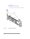
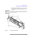
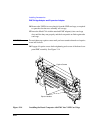
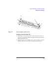
Typical Installation in a VME Card Cage
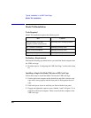
Configuring the VME Card Cage
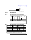
2 To determine the maximum current usage of the Model 744 memory
cards, either use Figure 3-1 and Table 3-2 (for Model 744/132L) or Table
3-3 (for Model 744/165L). You must work with the worst case power
draw to correctly determine power usage. Determine worst case power
draw by examining active memory bank configurations, using the follow-
ing steps:
a Examine your memory card configuration, noting which size card is in
each memory slot.
b The worst case active memory bank configuration depends on the slot
position of the memory cards, and the size of the cards. The 32MB
memory card has two banks per card, and the 16, 64, and 128MB cards
each have only one memory bank per card.
• When 32MB cards are used as a pair in memory slots 2 and 3 they
can use three memory banks concurrently.
• When used as a pair in slots 0, 1, or 2, the 32MB cards can have
two active memory banks.
• The 16, 64, and 128MB cards each have only one memory bank
that is active at any one time.
The worst case power draw would be if your system had 2 32MB
cards in slots 2 and 3 (these banks would be considered active, all
other memory cards/banks would be considered inactive). If you do
not have that configuration, the next worst case would be a 64MB
card in any slot (all other memory cards in the system would be inac-
tive), followed by 2 32MB cards in slots 0, 1, or 2 (all other memory
cards in the system would be inactive), followed by a 16MB card in
any slot (all other memory cards in the system would be inactive).
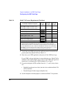
c Inactive memory banks are those banks on cards in your configuration
in addition to the worst case active memory banks, and must also be
added to the calculation.
d Fill in the information in Table 3-2 or Table 3-3.