


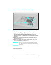
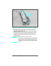
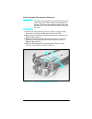
Note
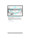
LaserJet 4 and 5 only: Note the orientation of
the bushing on the left side of the Fusing Roller.
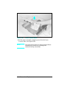
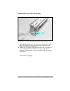
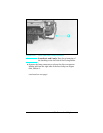
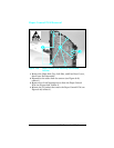
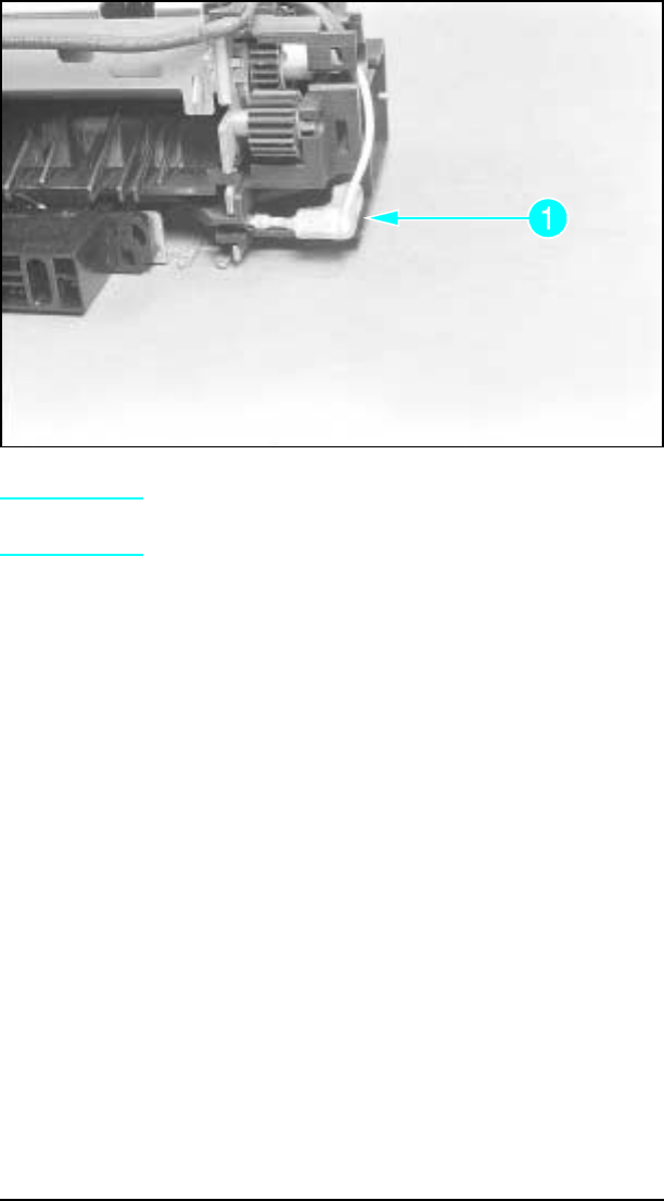
8 Squeeze the lamp connector to release the slip-on connector
locking tab from the right side of the heat lamp (see Figure
6-44, callout 1).
(continued on next page)
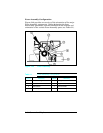
Figure 1-44 Gear Side Heat Lamp Connector
6-53 Removal and Replacement