


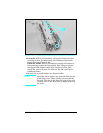
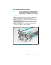
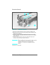
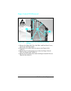
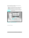
7 Remove the (1) screw that holds the Thermistor (see Figure
6-48b, callout 2).
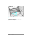
Note
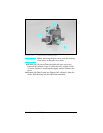
Ensure the thermistor cable is routed correctly
when assembling the fuser (see Figure 6-47).
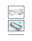
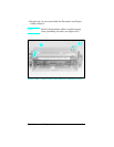
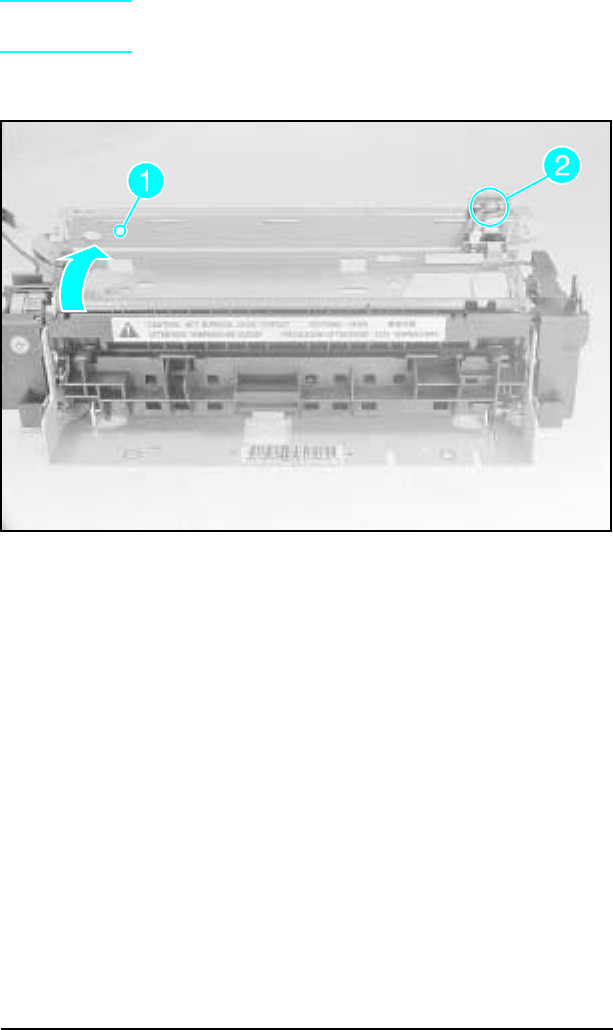
Figure 1-48b Upper Fuser Frame Removal (LaserJet 4 Plus)
6-58 Removal and Replacement